


Hardware components | ||||||
| × | 1 | ||||
 |
| × | 1 | |||
 |
| × | 1 | |||
 |
| × | 2 | |||
Software apps and online services | ||||||
 |
| |||||
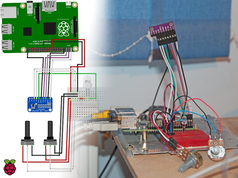
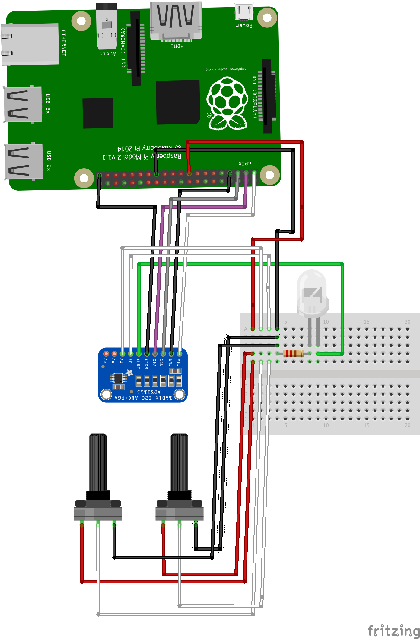
Probably it's not difficult to deploy the app. I've used the DMAP driver on the Raspberry Pi, but I suppose it would run with the default inbox driver, too. To make sure you won’t damage your IC, read the documentation. For example, the analog input must be between GND – 0.3V and VDD + 0.3V and it's recommended to clamp the signal with external Schottky diodes. In the remaining part in this page you can find the edited version of the documentation to clarify the various functions. More information can be found in GitHub wiki and README.md
.
This bit controls the current operational mode of the ADS1115.
- Continuous conversion mode
In continuous conversion mode, the ADC automatically begins a conversion of the input signal as soon as the previous conversion is completed. Continuously perform conversions. Once a conversion has been completed, the ADS1115 place the result in the conversion register and immediately begins another conversion.
- Single-shot mode
Automatically powers down after a conversion. ADC performs one conversion of the input signal upon request and stores the value to an internal result register. The device then enters a low-power shutdown mode.
InputConfigure the input multiplexer. You can select here witch input do you want to use.
- Differential
The ADS1115 A/D core measures a differential signal, that is the difference of two analog inputs. The fully differential voltage input of the ADS1115 is ideal for connection to differential sources with moderately low source impedance, such as thermocouples and thermistors. The differential input settings: AXY_DIFF is the name format, so we are measuring the AX - AY (where AX and AY are two different analog pins).
- Single-ended
When single-ended signals are measured, the negative input of the ADC is internally connected to GND by a switch within the multiplexer. The single-ended signal can range from 0V to supply. The single-ended input settings: AX_SE is the name format so we are measuring the AX - GND (where AX is an analog pin).
Configure the programmable gain amplifier. The PGA can be set to gains of 2/3, 1, 2, 4, 8 and 16. Table shows the corresponding full-scale (FS) ranges. The PGA = 2/3 setting allows input measurement to extend up to the supply voltage when VDD is larger than 4V, but it's not possible to reach a full-scale output code on the ADC because analog input voltage limits given in the electrical characteristics table.
Control the data rate setting. The rate of continuous conversion is equal to the programmed data rate. If the input signal contains frequencies greater than half the data rate, aliasing occurs.
Comparator polarityYou can set ALERT/RDY pin as active high or active low.
Comparator latchingEither window or traditional comparator mode, the comparator can be configured to latch once asserted. This setting causes the assertion to remain even if the input signal is not beyond the bounds of the threshold registers. This latched assertion can be cleared by issuing an SMBus alert response or by reading the Conversion register witch means you have to call one of the read methods.
Comparator queueThe comparator can be configured to activate the ALERT/RDY pin after a set number of successive readings exceed the threshold. The comparator can be configured to wait for one, two, or four readings beyond the threshold before activating the ALERT/RDY pin by changing the comparator queue settings. There are four of them: assert after one, two, four or disable the comparator.
Conversion ready modeThe ALERT/RDY pin can also be configured as a conversion ready pin. This mode of operation can be realized by calling ADS1115Sensor's TurnAlertIntoConversionReady() function. The comparator polarity continues to function and the comparator queue settings can disable the pin; however, the comparator mode and comparator latching no longer control any function. When configured as a conversion ready pin, ALERT/RDY continues to require a pull-up resistor. When in continuous conversion mode, the ADS1113/4/5 provide a brief (~8μs) pulse on the ALERT/RDY pin at the end of each conversion. When in single-shot shutdown mode, the ALERT/RDY pin asserts low at the end of a conversion if the COMP_POL bit is set to '0'.
The ADS1114/5 are each equipped with a customizable comparator that can issue an alert on the ALERT/RDY pin. This feature can significantly reduce external circuitry for many applications.
- Traditional comparator
The ALERT/RDY pin asserts (active low by default) when conversion data exceed the limit set in the high threshold register. The comparator de-asserts when the input signal falls below the low threshold register value.
- Window comparator
The ALERT/RDY pin asserts if the conversion data exceeds the high threshold register or fall below the low threshold register.
- Test the voltage values:
- Test the comparator:
Enable comparator in comparator queue, then write into the threshold register. It works properly. I couldn't test the conversion ready pin mode yet.


Comments
Please log in or sign up to comment.