


Hardware components | ||||||
 |
| × | 1 | |||
 |
| × | 1 | |||
| × | 1 | ||||
| × | 1 | ||||
Software apps and online services | ||||||
 |
| |||||
Hand tools and fabrication machines | ||||||
 |
| |||||
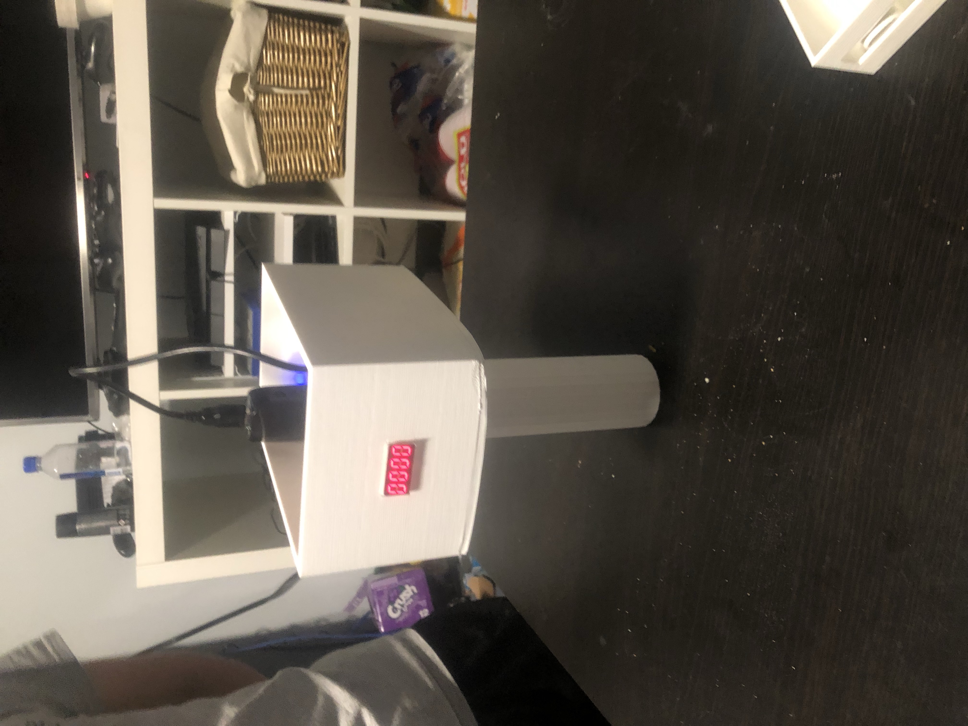
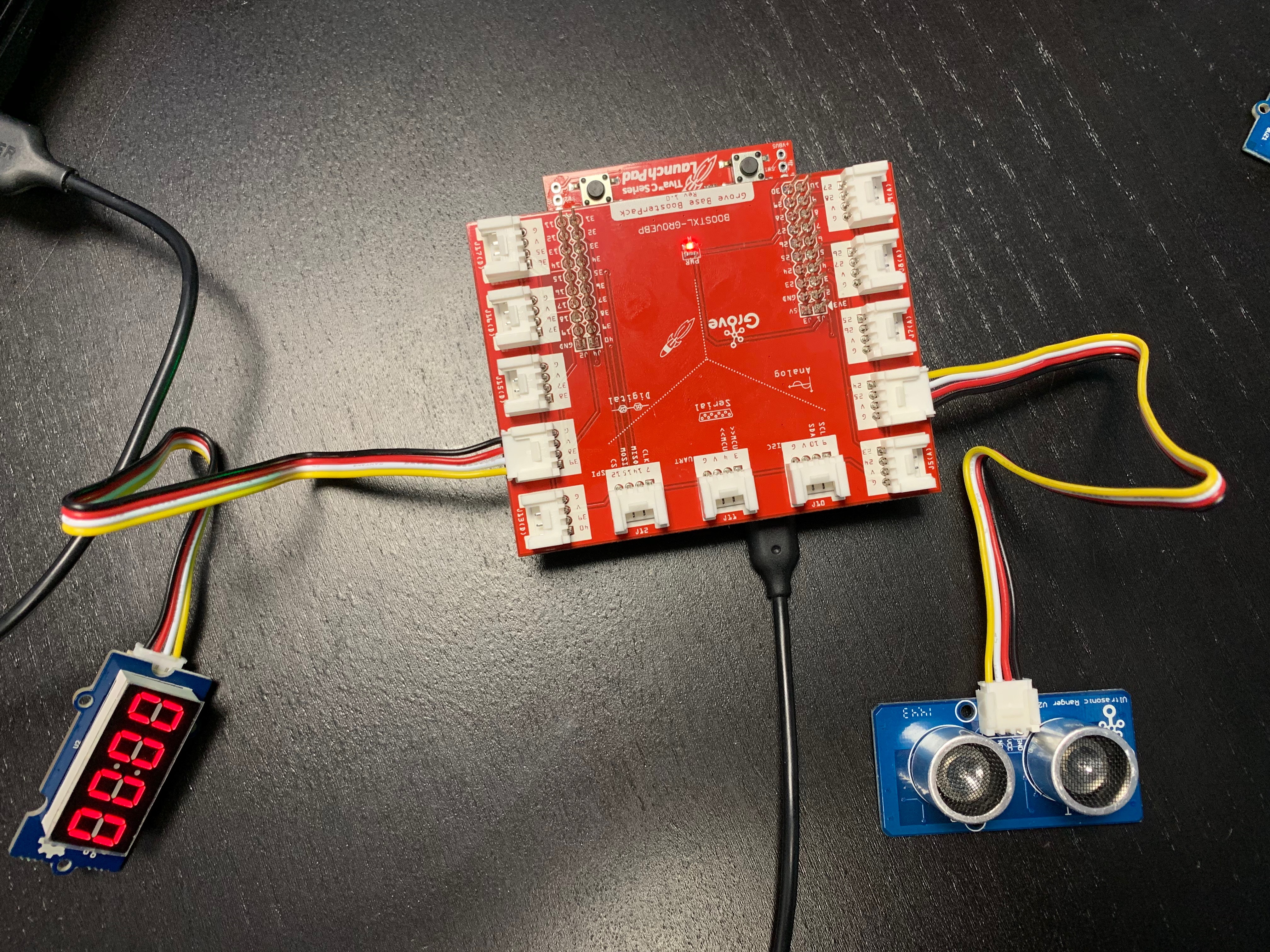
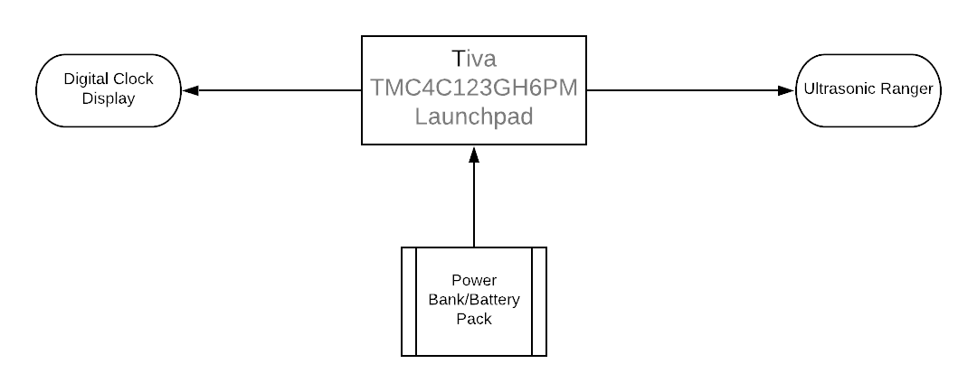
We’re Team I’m Going to the Bank. Our project is a radar gun, a piece of equipment often used by police officers to measure the speed of moving objects. The two modules we used are the digital display and the Ultrasonic Ranger We 3D printed the shell of the radar gun and coded the Tiva TMC4C123GH6PM Launchpad with Energia.
Operation Instructions:
1. Make sure the power bank/battery pack is charged and everything is plugged in.
2. Point the radar gun in a direction where the moving object will pass in front of the gun.
2. After the object passes in front of the gun, wait until the speed of the object(in centimeters per second) flashes on the display.
The theoretical and mathematical base of the project:
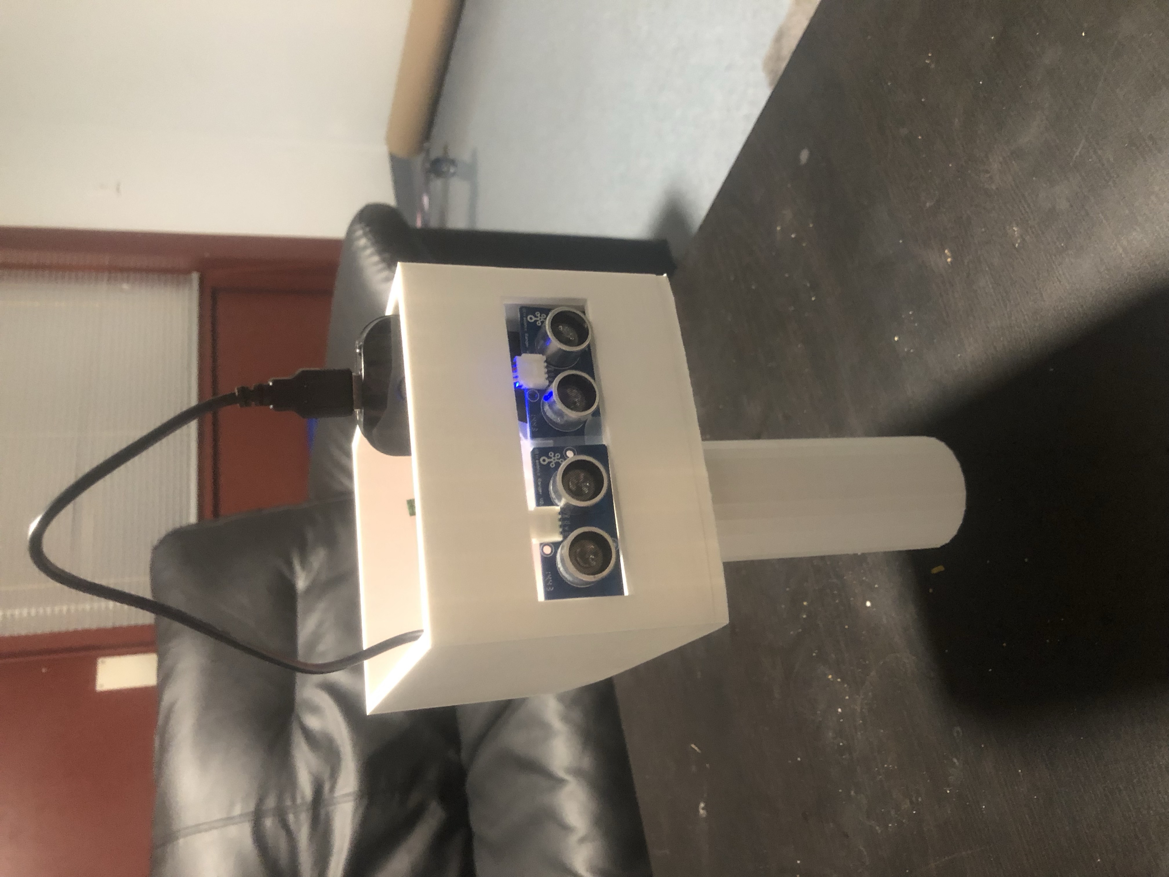
- To make the gun work accurately, as previously mentioned, we used two Ultrasonic Ranger components side by side. We then realized that each Ultrasonic Ranger produces a cone-like range of waves that we decided to call the "detection area."
- Since each one of the Ultrasonic Rangers produce one of those "detection areas" and also since they are both attached relatively close to each other, then one can easily see that there exists a common "detection area" between the two Ultrasonic Rangers which is basically the intersection of the two cones(Which is a cone itself!).
- When detecting an objects speed we keep track of whether the object is in the common area or not by having a Boolean condition which tests if the difference between the two ultrasonic readers' readings is less than an epsilon value(a really small arbitrary value) or not.
- When an object enters the range of one of the two ultrasonic rangers but not the other, nothing happens. However, when the objects enters the "common area" we save the smaller of the two first readings of the Ultrasonic Rangers (one of the triangle legs) and also start a timer and keep the timer working till the object exists the common area, and just before it exits we save the minimum of the last readings by each of the two Ultrasonic Rangers(the second triangle leg) and by using the two leg readings and and estimated theta value of the common area Cone we used the cosine rule to compute the horizontal distance moved. Finally, given the distance and the time we can compute the speed v = d/t.
A really rough sketch of the situation can be seen below.
Application Part 1.0: After studying the math behind the certain setting of sensors we started writing the code that puts everything together. The calculations were made as described above to measure the speed instantaneously. Code, debug, repeat...
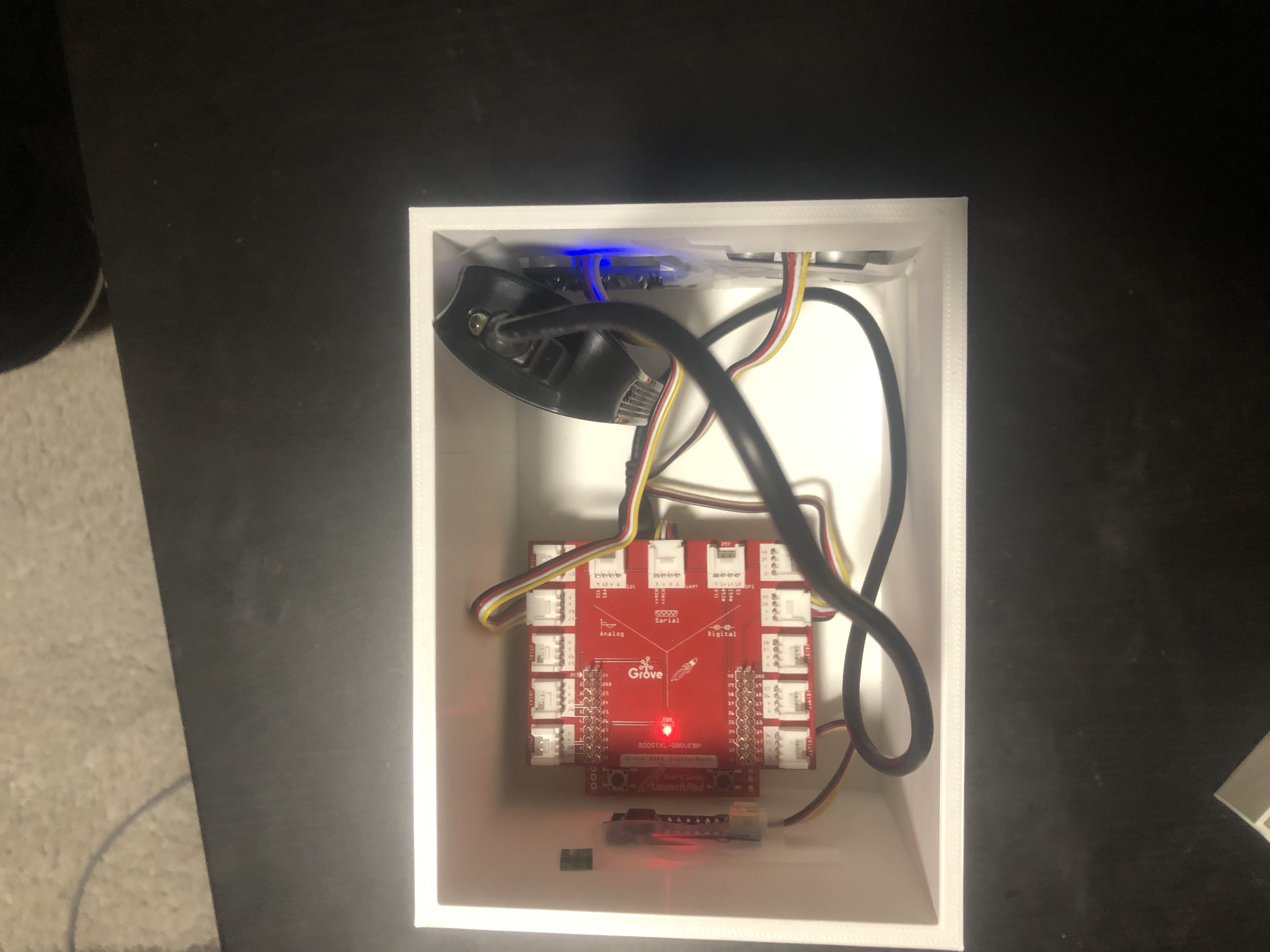
Application Part 1.1: We designed the body (seen in the attachments) that holds the launchpad and the sensors using SketchUp software.
Application Part 1.2: We used the OEDK to 3D print the designed body. Part 1.1 the 1.2 were done in this order parallel to writing the code (part 1.0).
Testing: After having the code running and the gun ready, we made a couple of tests and adjusted the code to better fit the results and exact dimensions of the body.
Finally: We presented our work in front of an awesome audience.


Comments
Please log in or sign up to comment.