Overview
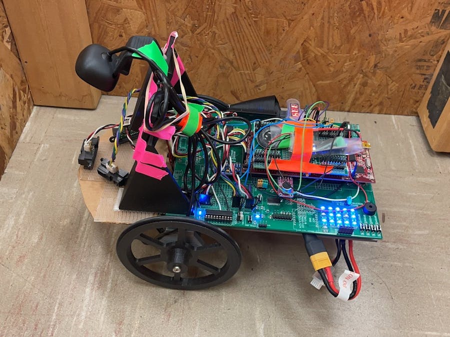
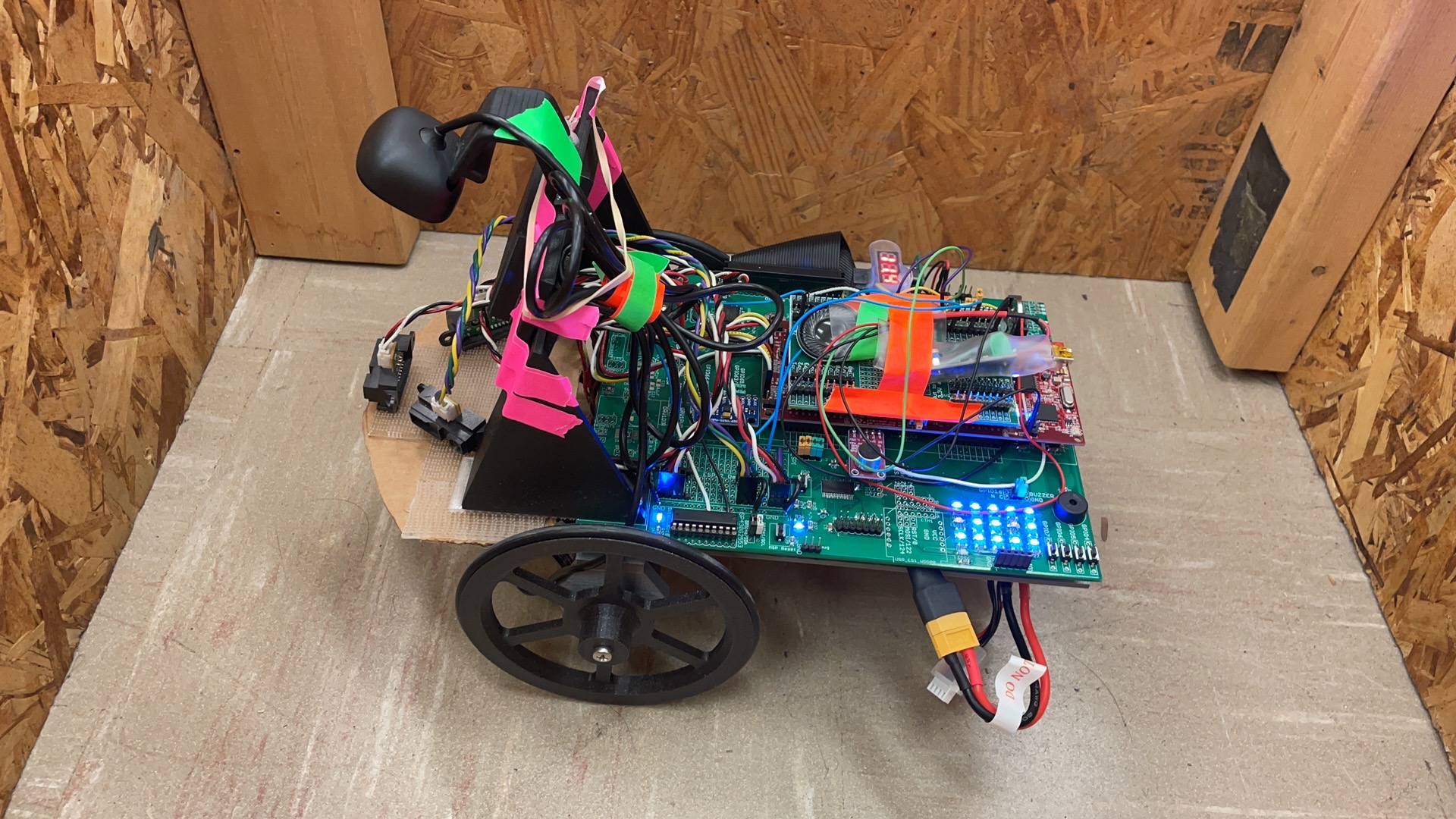
The team built a robot base from ME461. The project is based off the two-wheeled robot with a caster. The three-wheel robot is controlled by a TI launchpad F28379D. Besides, the three-wheel robot also contains a microphone, two wheel optical encoders and a 10 DOF IMU. To make the robot car capable of doing more intensive computation and communication, the team decided to add a Raspberry Pi 4 on it. A USB camera compatible with the Raspberry Pi 4 was mounted on the robot car for visual perception abilities. To perform obstacle avoidance function, the robot car is equipped with three range-finders on the front, left and right side. The team initially planned to have three ultrasonic sensors on each side, but was informed that multiple ultrasonic sensors might not work well due to noise and interference. As such, the team proceeded to substitute the ultrasonic sensors with three infrared distance sensors. The team also added a TI mini-speaker to output different horn sounds at designated intervals associated with obstacle avoidance. The horn consists of different sets of sound inputs that can be played during obstacle avoidance states using command input in the code.
The robot was put in a series of states. Each state serves a designated robot operation command, such as the “straight line routing” mode, which is the default operating mode, the “wall riding” mode when the front infrared distance sensor detects obstacles and commands the robot to go around them. There will also be several intermediate states between the line following and wall riding. For example, the vehicle will determine to use either right-wall or left-wall following depending on the location of the dash line. If the dash line is on the left, left-lane switching is allowed; similar to a real-life scenario, a left-wall following decision will be made. The states will be organized in a finite state machine so that the robot will transit among each state based on the sensor readings and camera images. A USB camera is used to locate different lines on the “high way” designed by the team. The differentiation between each line will serve to initiate the direction of wall-following. The vehicle utilizes a camera connected to Raspberry Pi 4 to do the visual recognition of the lines around the robot. An OpenCV-based algorithm was developed to detect if the lines are solid or dashed, which will determine the legal states of the robot (lane switch possible/impossible). For example, if the lines on both sides are solid, then wall-riding mode is illegal. If the left line is dashed, then the left-wall-riding mode is allowed.
A MB1010 LV-MaxSonar-EZ1*1 sonar was planned to be mounted at the front of the robot car, while the two infrared sensors were mounted on the two front diagonal corners and facing outside 45deg with respect to the central axis of the robot car as planned. The sonar was planned to sense any obstacles in front of the robot when it is performing a straight line following, and the infrared distance sensors facing 45deg towards left and right will be sensing the side distance between the robot car and the obstacle. When the obstacle at the front of the vehicle is detected, the robot will then switch to direction changing mode and wall riding mode until the obstacle is out of the front sensor’s range. Data was obtained via the sonar’s Analog Voltage output. The sonar will be communicated with F28379D with the ADC peripheral. Similarly, since the infrared distance sensor have single analog voltage output, it will also be communicated with F28379D with the ADC peripheral. The range data will be used as an important parameter to determine the changing between different machine states. The team then created two trendlines to visualize the analog voltage output from both the sonar and infrared sensors.
However, when conducting the actual obstacle avoidance testing, it is shown that the MaxBotix sonar cannot produce stable reading due to unfiltered electrical noises. To resolve this, a Resistor and Capacitor(RC) filter and a shielded cable are recommended as instructed by MaxBotix. Due to limited time constraint, the team decided to change the sonar to a third infrared distance sensor for more stable reading. The team also found that the infrared distance sensors have an initial threshold distance for activating accurate distance reading, therefore the infrared distance sensors were remounted as follows, allowing more space between the sensor and obstacle. The communication between the F28379D launchpad and the three infrared distance sensors is achieved through the ADC peripheral using ADCINA2, ADCINA3 and ADCINA4. The analog voltage output is converted with a factor of 3.0/4095.0, inverted by subtracting it from 3.0, and averaged from every five outputs for better obstacle recognition performance.
Line recognition
The line recognition is achieved by a USB camera and a Raspberry Pi using OpenCV. Using a blob search by area and an HSV color filter, the Raspberry Pi code was able to recognize and output the keypoint’s position and size of each block in a specific color (orange in this case). Since the camera mounted at the front will always capture the front view of the car, the left and right line specification was done by splitting the camera frame coordinate into left and right halves. If a keypoint is located at the left half of the camera frame coordinate, it will be categorized as a part of the left line and vice versa. Algorithmically, if any keypoint on any side has a size that is larger than a threshold, that side will be determined to be a solid line. If no block on one side has a size larger than the threshold, that side will be determined as a dashed line. The primary purpose of the line recognition is to send a legal flag to F28378D continuously so that the car can know which way to turn when a passing operation is needed. Different legal flags were established with different scenarios:
Legal flag ‘A’: left is a dashed line and the right is a solid line, meaning left passing only.
Legal flag ‘B’: left is a solid line and the right is a dashed line, meaning right passing only.
Legal flag ‘C’: both sides are dashed lines or no lines, meaning all passing is allowed. However, the car will be set to left passing by default.
Legal flags A, B, and C refers to legal flag 1, 2, and 3 in the state diagram, respectively.
Although Pi continuously sends legal flags to F28378D, the flags are stored in a variable that will only be checked when an obstacle is detected and a decision has to be made.
Control AlgorithmBoth motors are powered by a PWM signal with its duty cycle dependent on a "control effort" variable. The control effort is calculated using a PI controller. Steering is completed by using a "turn" variable that is also a part of the PI controller. While the robot is in wall following mode, the turn variable is calculated using proportional control based on the difference between the voltage reading of one of the side-mounted infrared sensors and the voltage reading at the desired distance.
The logic behind the PI controller can be shown in the block diagram below.
Sample codes from the project main code are provided below.
errturn = turn + (VLeftK-VRightK);
// error term calculated based on the turn variable and difference in wheel velocities

//left
errLK = Vref - VLeftK - KP_turn*errturn;    // error term of velocity
ILK = ILK_1 + (errLK+errLK_1)/2.0*0.004;    // integration using trapezoidal rule
uLeft = Kp*errLK + Ki*ILK;          // control effort
//right
errRK = Vref - VRightK + KP_turn*errturn;
IRK = IRK_1 + (errRK+errRK_1)/2.0*0.004;
uRight = Kp*errRK + Ki*IRK;

// these 2 lines of code below are used in state 30 (right wall following)
turn = Kpr*(rightref - aRIR);
// aRIR is the average infrared voltage reading from 5 samples

Vref = 0.15;      // desired velocity of the robot car
In the sample code above, all error terms refer to the difference between the desired value of each variable and their actual values.
Horn Design
The horn design aimed to create varying horn sounds for different states of the robot. Each of the three states consisted of a horn sound created by combining two sine waves. The sine waves differed from each other via frequency (500-1500) and amplitude (0.75 or 1.5) of the sine wave and the combination. In addition, periods of no sounds were played in between each frequency to create the honking sound and each series of cases ended with a period of no sound to make sure the sound did not continue to play after the state ended. To play the horn sounds at the correct time a flag was created for each individual sound that called a certain series of cases. The three sets of cases were a horn noise when the robot recognized an obstacle, when the robot returned to the line following mode, and when the robot reached a point where it recognized an obstacle when surrounded by solid lines. The parts needed for this were the mini-speaker, sound amplifier, and 6 wires.
Demo Video Link (In case video attachment does not work):
Demo 1:
https://youtube.com/shorts/0V-nJQ2oRWo
Demo 2:
https://youtube.com/shorts/iXFANy6Yzhg


Comments
Please log in or sign up to comment.