This project is a subsystem of a larger project that I was a part of for my UW Bothell Sensors and Sensor Systems elective class in Autumn 2018. That project can be found HERE. This project will highlight the use of the PmodGPS from Digilent as a position locator and guide to a reference point. This can be helpful for hikers, hunters, or other navigators in situations without signs or other clear location/direction markers.
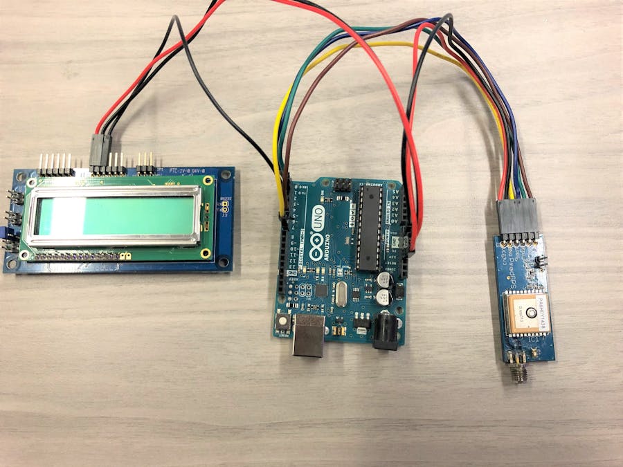
DescriptionThis project uses and Arduino Uno microcontroller, PmodCLS LCD screen from Digilent, and the PmodGPS also from Digilent. The Arduino Uno was encouraged for us to use for easier programming rather than Verilog or some other HDL. Once operational, this project will display the user's latitude, longitude, altitude, distance to a fixed reference point, angle bearing towards a fixed reference point, speed of the user, as well as other data should the programmer choose to implement as there are many other functions available for the PmodGPS. This system can be powered by a USB connected battery for mobile application. Just program the Arduino Uno, disconnect from your computer, plug in the USB battery, and the Arduino Uno should continue operating as normal. The reference point is set at the time of system reset. This can be manually triggered by pressing the Reset button on the Arduino Uno.
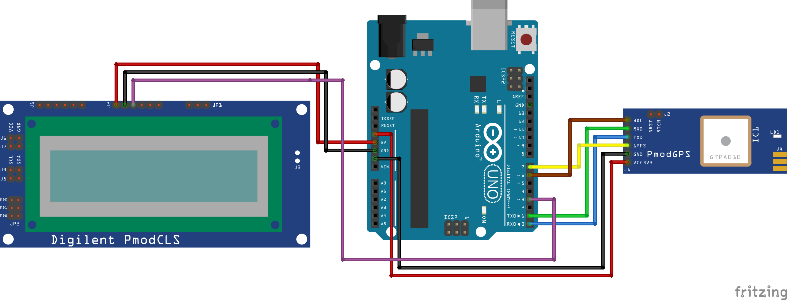
ConnectionsPmodCLS: I used a PmodCLS for my LCD screen simply because it was available, I had example code for using it in the Arduino IDE, and it was simple to implement. The PmodCLS uses a 5V power, ground, and an RX line for receiving data from the Arduino Uno to be displayed. These connections are located on the "top" row of pins in the J2 section. The backside of the PmodCLS indicates which pins are V+, GND, and RX. TX is not needed since the screen will not be sending data back to the Arduino Uno. The RX connects to PIN X on the Arduino.
PmodGPS: The PmodGPS uses a UART connection with the Arduino Uno. Connect the TX on the PmodGPS to the RX on the Arduino Uno and the RX on the PmodGPS to the TX on the Arduino Uno. NOTE: this connection needs to be done after uploading the code to the Arduino Uno because the Arduino IDE uses the serial port for code uploading and the PmodGPS will disrupt that connection. The 1PPS pin is a "1 Pulse Per Second" output pin that is synchronized with the GPS time. Connect the 1PPS pin to PIN X on the Arduino Uno. The 3DF pin indicates the status of the user’s positional fix. When the module has a constant fix this pin stays low, if the module is unable to get a fix then the pin will toggle every second. I am still a bit unsure as to what this exactly means, I did not have any performance difference whether the position was "fixed" or not. Connect the 3DF pin to PIN X on the Arduino Uno. Lastly, connect the GND and the 3.3V.
USB Battery: For a mobile application, first upload the code to the Arduino Uno, connect the TX/RX of the PmodGPS, then connect a USB battery to the Arduino Uno.
Below are some sample output displays on the LCD screen. All the components are being held in a fanny pack, as that was part of the bigger project mentioned in the beginning of this project.


_ztBMuBhMHo.jpg?auto=compress%2Cformat&w=48&h=48&fit=fill&bg=ffffff)


Comments
Please log in or sign up to comment.