

Hardware components | ||||||
_ztBMuBhMHo.jpg?auto=compress%2Cformat&w=48&h=48&fit=fill&bg=ffffff) |
| × | 1 | |||
| × | 1 | ||||
 |
| × | 1 | |||
 |
| × | 1 | |||
 |
| × | 1 | |||
 |
| × | 1 | |||
Software apps and online services | ||||||
 |
| |||||
It's almost the festive season and numbers of shops have started putting out their festive decorations, I thought that it’s about the right time to build some musical fairy lights!
I'll be using the following:
- 12 x LED's
- 12 x Current limiting Resistors
- 1 x ULN2803 Darlington Transistor Array
- Some Jumper Wires
- 1 x piezo Speaker
- 1 x Breadboard and
- 1 x Arduino
- To make the string of fairy lights I used 5 wires from an Ethernet cable
//GLOBAL VARS
int barTime = 1200;                                     // 8/8 = 1000ms
byte nrLEDS = 4;                                         // 4 Base LEDs, You can add many in parallel
byte leds[] = { 3, 4, 5, 6};
byte speaker = 11;
byte patternLength = 64;                                 // pattern Length
byte songLength = 51;
const byte song[] = {                                    // Jingle Bells Data
 29, 2,29, 2,29, 4,29, 2,29, 2,29, 4,29, 2,32, 2,25, 3,27, 1,29, 8,30, 2,30, 2,
 30, 3,30, 1,30, 2,29, 2,29, 2,29, 1,29, 1,29, 2,27, 2,27, 2,29, 2,27, 4,32, 4,
 29, 2,29, 2,29, 4,29, 2,29, 2,29, 4,29, 2,32, 2,25, 3,27, 1,29, 8,30, 2,30, 2,
 30, 2,30, 2,30, 2,29, 2,29, 2,29, 1,29, 1,32, 2,32, 2,30, 2,27, 2,25, 8
}
;                                                        // The Structure is Note Number then
                                                        // NoteLength in 8th's
const byte pattern[] = {                                 //Pattern Data
 0b0001,0b0010,0b0100,0b1000,                           //Bits corrispond to Leds in Array
 0b0001,0b0010,0b0100,0b1000,
 0b0001,0b0010,0b0100,0b1000,
 0b0001,0b0010,0b0100,0b1000,
 0b1000,0b1100,0b0100,0b0110,
 0b0010,0b0011,0b0001,0b1001,
 0b1000,0b1100,0b0100,0b0110,
 0b0010,0b0011,0b0001,0b1001,
 0b1010,0b0101,0b1010,0b0101,
 0b1010,0b0101,0b1010,0b0101,
 0b1010,0b0101,0b1010,0b0101,
 0b1010,0b0101,0b1010,0b0101,
 0b1100,0b0011,0b1100,0b0011,
 0b1100,0b0011,0b1100,0b0011,
 0b1100,0b0011,0b1100,0b0011,
 0b1100,0b0011,0b1100,0b0011,
 };
First off I declare my variables, the interesting ones being Song and Pattern:
- The song stores the tune; in this case it is Jingle bells.
- The pattern stores on and off positions in the bits of the values in the array.
//FUNCTIONS
int noteToHz(int note) {                                 // Convert a Note Nr. to Frequency
 float freq = 440 * (pow(1.059463094359,note-21));       // -21 gives you note 1 at C3 (I Think)
 return int(freq);                                       // Results are accurate to 1hz
}
void lightLEDs(byte PORT_X) {                             // Control LED's State
 for (int q = 0;q<nrLEDS;q++) {
   digitalWrite(leds[q],bitRead(PORT_X,q));
 }
}
The two functions I have will do the following:
- Calculate the frequency for the tone function in the loop
- Switch on or off the LED's depending on the value passed to the function
void setup() { //setup OUTPUT pins
 pinMode(speaker,OUTPUT);
 for(int t = 0; t < nrLEDS; t++){
   pinMode(leds[t],OUTPUT);
 }
}
In the setup function I set the pins required to OUTPUT.
void loop() {
 // Music Loop
 for (int t = 0; t < songLength; t++) {
   // Notes, Length and play the melody
   int note = noteToHz(song[t * 2]);
   int length = ((song[(t * 2)+1] * barTime) / 8);
   tone(speaker, note,  length - 50);
   // Flashing Lights!
   lightLEDs(pattern[t % patternLength]);
   delay(length);
 }
 // Silence Loop
 int randomSilence = random(1000,5000);
 for (int t = 0;t<randomSilence;t++){
   lightLEDs(pattern[t % patternLength]);
   delay(barTime/4);
 }
}
I have 2 loops in the Main Loop function. A song loop and a silence loop. The song loop will read the data from the song array, play the note using the tone function. The song loop will:
- Read the data from the song array,
- Play the note using the tone function then
- Light up the LED's, reading pattern array.
In the Silence loop:
- Only the LED's are lit up.
Plug the Arduino in and upload the code. (Then unplug it)
I'm going to start out with the string of lights:
- I used wire from an Ethernet cable and soldered 3 LED's in parallel four times, making sure to space out the LED's evenly over about 2 meters
- I soldered the Anode of each led to a single wire.
- Then the Cathode of each LED to 4 separate wires. With a resistor of course
- I repeated this process 3 times to get a string of 12 LED's and I put header pins on the end of the 5 wires
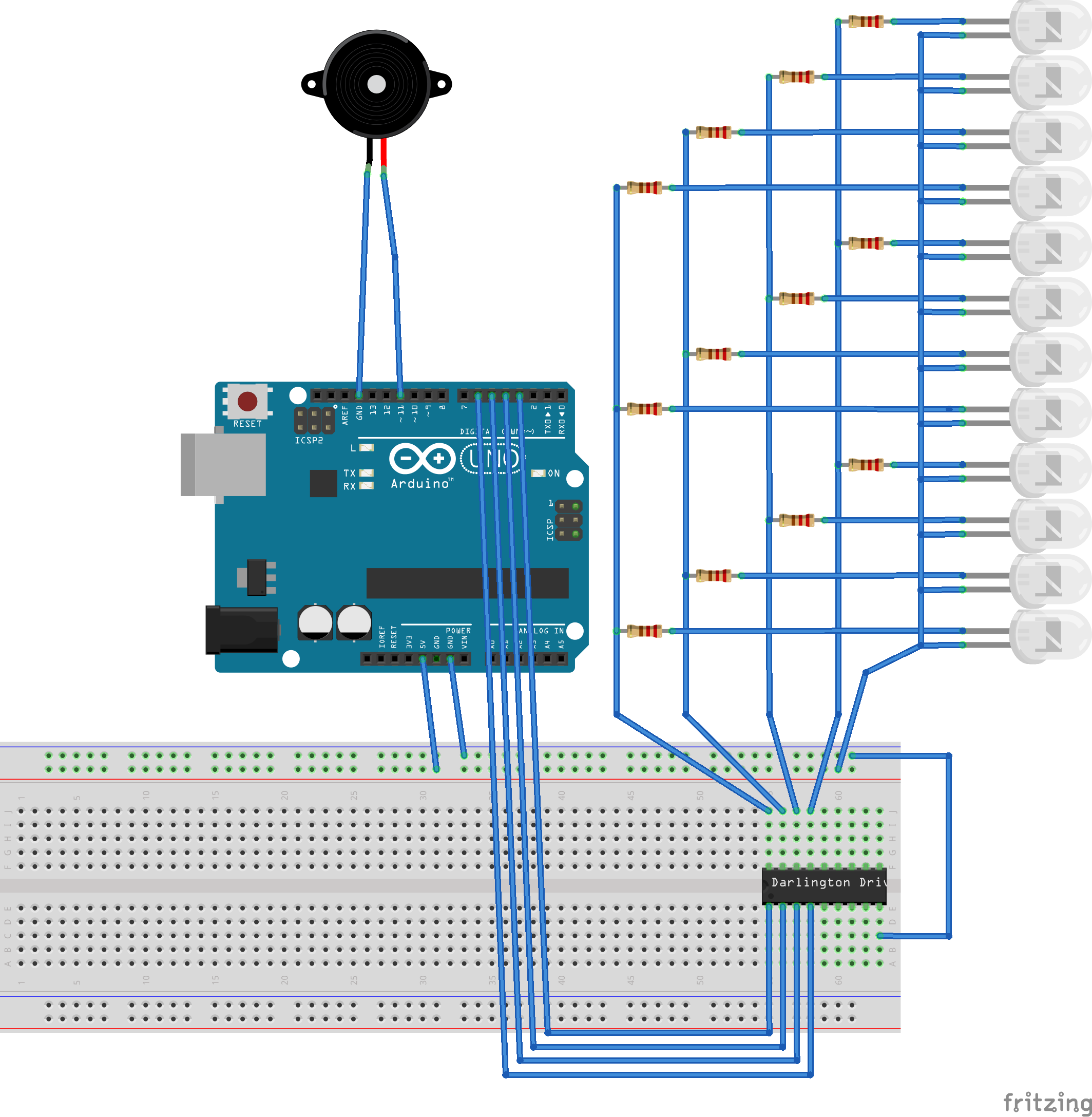
Now that I have the string of LED's head on over to the breadboard:
Connect the Positive and ground rails to the breadboard:
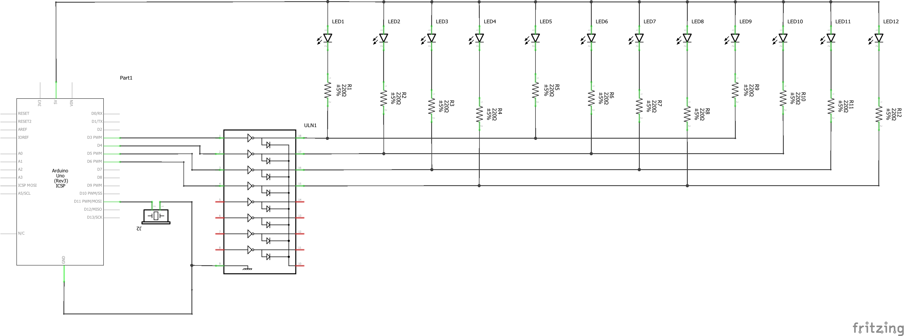
Place the ULN2308 Chip onto the breadboard. The ULN2308 is a transistor array chip; from the data sheet I can see:
- That pin 1 is an input that turns pin 18 "ON"
- Pin 2 turns 17 on. Etc.
- Pin 9 is ground
- Connect Pin 9 of the chip to the ground rail
- Connect the positive rail to a terminal strip, one strip above pin 18.
You will see why in a minute:
- Connect pin 1 of the chip to pin 3 of the Arduino
- 2 goes to 4
- 3 of the chip goes to 5 and
- 4 goes to pin 6 of the Arduino
Place the LED string onto the breadboard. Where the common anode wire is connected to the strip connected to 5 volts. The rest of the fairy light pins should go to pin 18, 17, 16 and 15 of the chip.
Connect the Piezo Speaker between 2 terminal strips:
- Connect the negative pole of the Piezo element to ground and
- The other end of the speaker to pin 11
I have a string of lights that will randomly play jingle bells to remind me that it is the festive season.


Comments