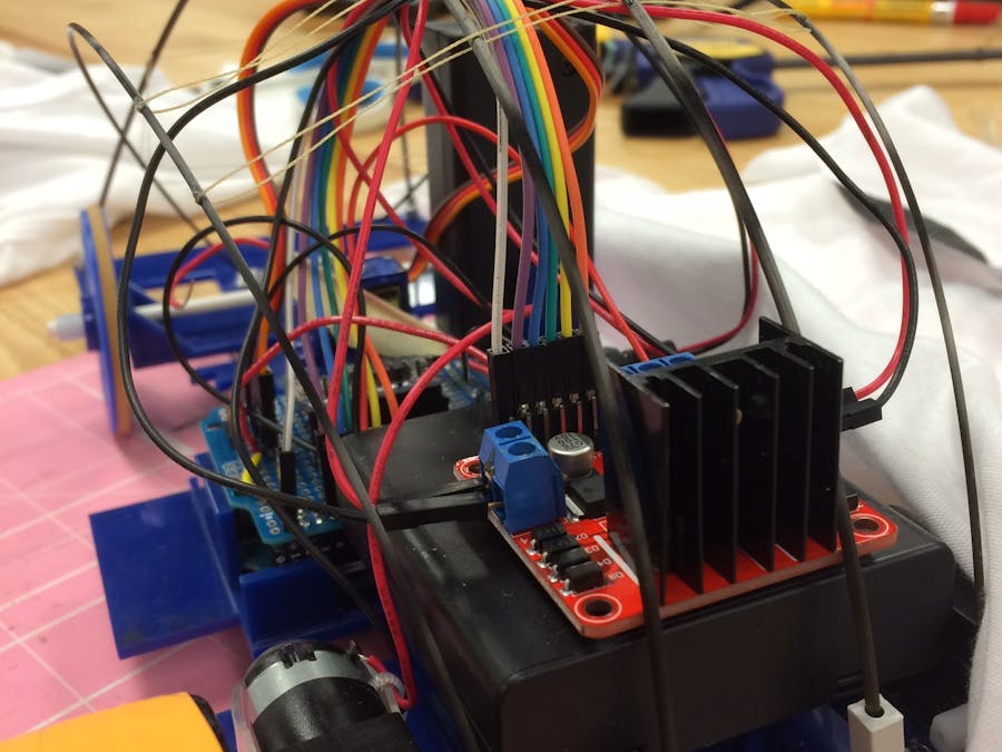
The below album highlights quick changes I made since last week. I soldered the connections of the Bluetooth module, as well as 5V/GND channels and the header pins for each module. I did this all on an Arduino shield! As such, the Arduino is entirely removable.
Some other quick fixes include completely replacing the AA and 9V batteries, and buying an entirely new L298 controller (since the last one had only two working output pins, and I need four).
Fritzing Diagram for the Bluetooth module (from the Adafruit Tutorial):
- I used the compilation of the two below schematics for my car.
My idea of evolving the car I had already build was not just to solder the components and make the car more tidy and compact, but to build some kind of body to house these components. To do this, I chose to make a frame on my acrylic body made out of carbon fiber rods, which fit into grey pieces of tubing.
A few problems did arise with the frame. Number one, the carbon rods are extremely strong! I had to toy with many designs and thicknesses for the rods so that they would not break my car. The first iteration of carbon fiber rods I placed on the body bent the acrylic so much that much of the acrylic became disjointed or dislocated. So I rebuilt the frame and tried again, with a smaller diameter rod.
Bear in mind that these tubes are more dangerous than your typical hobby support material! The dust created from cutting these is very dangerous, and frayed edges can leave dangerous splinters in your skin with different inflammatory effects than traditional splinters. To try to mitigate these issues, I wore gloves, glasses, and kept the rod wet while I cut it. Then I sanded the cut sides, all the while not breathing.
I found an appropriate diameter for my body, cut the lengths, and stuck them on the car using plastic tubing to hold the rods. I tested the adhesion between a small piece of plastic tube and acrylic with CA glue, to ensure that this bond was strong enough. It turns out it's plenty strong.
Next, I had to create a bumper that extended out of the front of the car to hold the carbon supports that extend from this to the back of the car. I tested the turning radius in the album below to make sure that the wheels would not touch this bumper:
Here are the cuts I made to make the bumper in the front and two side bumpers, as well as supports for the bottom of the car to hold these in place:
Below are a few pictures (3) of the bumper attached, with the first support tubes in place:
Here the rods are cut and attached. The two middle-most rods are a slightly thicker diameter than the outer two. This was because the car could realistically only support the tension from two of these strong rods, so the other rods needed to apply less bending force on the car. I figured the most instrumental supports were the top two, so I made those the strongest.
All the rods connect to the back of the car, to independent tubes. The body was designed so that when it is wrapped in material, no prominent features (like the protruding 9V battery pack) would be visible.
I originally intended to stretch spandex over this carbon fiber tubing, which would have been incredibly awesome. However, the closest material both Chris and myself could come up with between us was a stretch shirt that I had. So in practice, my idea was not as aesthetically pleasing as I had hoped.
Very final product:
The dark spot where that "hole" is is really just a dark paint stripe. The polyester shirt I cut to stretch over the car had writing on it, and I did my best to cut only white shirt to use.
The project is finished! I'm happy with my work and I'm happy with the things I learned on the way.


Comments