Project
I began by breadboarding the setup, so I didn't make trivial mistakes when soldering. I almost did everything right the first time I soldered.
The setup
The Arduino powers the breadboard. The servo is first to draw from the 5V input, and has a digital input from pin 3, and is finally grounded to the negative channel on the breadboard.
The channel where the servo receives digital input from pin 3 is also attached to an LED (green), so the LED will vary in brightness according to the signal input from pin 3.
Next, a parallel circuit of 2 LEDs draws from the 5V input, and is wired to the ground.
Here is what the breadboard looks like:
Tools:
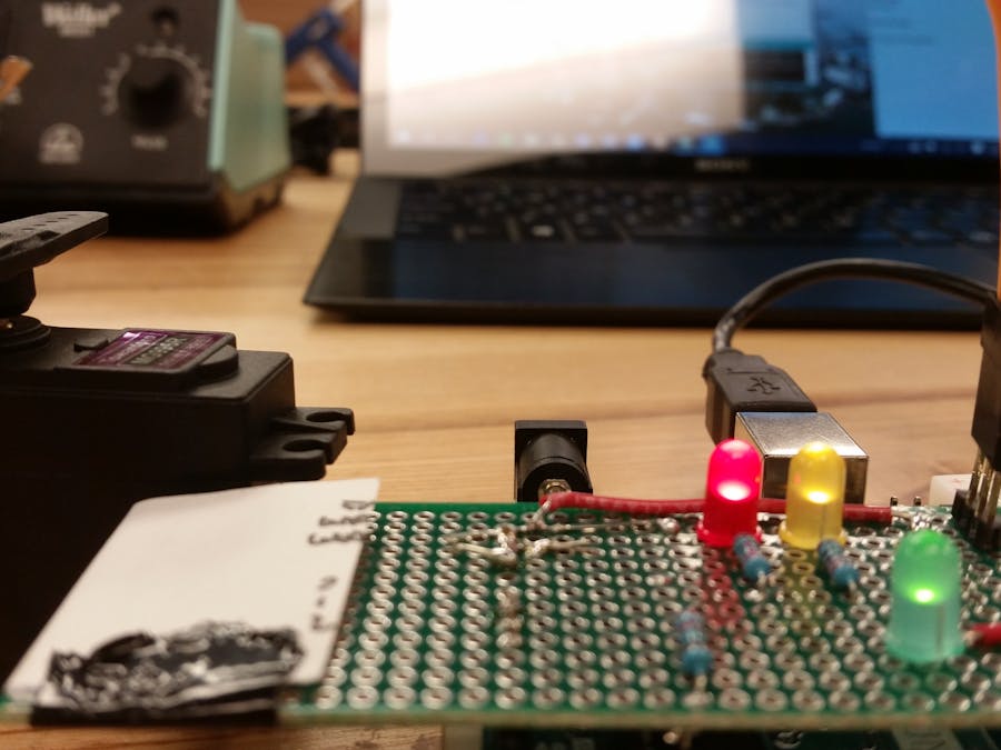
As far as circuitry goes, the perfboard circuit was the exact same as what I described above. For the servo, I used long pins to attach to, that way it is removable. I tried as best as I could to keep the board clean and organized.
In transferring the exact same circuit from the breadboard to the perfboard, I could not seem to get the servo to work consistently. It seems to turn on and run sporadically. Interestingly enough when the servo is removed from the circuit, the system functions exactly as planned. The two LEDs stay on, and the green one attached to digital pin 3 blinks very very fast. As soon as the servo is attached, the green light dims practically to nothing/turns off, while the other two LEDs remain on.
Servo grounded (removed):
Servo integrated in circuit:
×
Drag and drop images or click to select some from your file system
Here is a video of the servo dilemma in action.
Troubles I experienced:
The first iteration of soldering, I mistakenly attached the 5V input of the servo motor in a parallel circuit with my LED to pin 3. This was a mistake, as the servo shouldn't be drawing power from the digital pin, rather, it should draw from normal 5V from the Arduino. I think the reason I made this mistake was because of my poor color choice for the wires!


Comments
Please log in or sign up to comment.