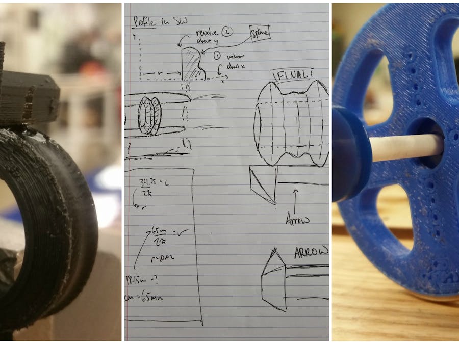
Part 1: 3D Printed Ring
This was my first time 3D printing anything, but I quickly figured out how to print efficiently and what settings are optimal to use. For example, I ran into some issues with the layer height set to .2mm, as the resolution of my piece decreased significantly and the profile was much less defined.
After 5 iterations, I finally had two working rings! One ring snapped off of the build plate in the final few layers, as Chris and I had cleaned the build plate prior to printing and I did not apply enough glue. The another one had a poor figure due to the setting of the layer height, and lost its definition.
Another problem I ran into was the warping of the plastic after some prints. You can see the bottom and back of the nearest arrow in this picture has a slope up, as it warped during my print.
The ring in the middle was the worst, as it has a smaller arrow on top, and both the arrow and the ring were made with a .2mm layer height. They have much less aesthetic appeal than the two on the left or the right.
The Sketch:
I am a big fan of geometrically defined pieces, which is where i got the idea for this ring. It consists of two parts: the actual ring and an arrow on top. The actual ring was designed flat on one end (the wearer's end) and splined on the other, then revolved around the z-axis to make a 3D figure. This detail is in the top left of the sketch below!
Also included are placement of the arrow, wearability, and the arrow's initial design.
The fit:
It works nicely on my pinkie, and it's a tight squeeze on my ring finger. With butter available it works.
Part 2: Laser-cut name tag
The design of my name tags are inspired by the design in Jacobs Hall, where the halftone holes in the wood make a 3-dimensional-looking hand. I fought with Adobe Illustrator to create my own half-tone images, which ended up only doing half of what I wanted to. I originally wanted to cut the halftone holes into my name tag, but after that design proved to be far too difficult for me to manifest, I stuck to a halftone raster.
On the right is the first design. The left is the slightly sleeker second design, where my name is embossed rather than rastered. The second time around, however, I think I may have made a mistake on the material settings and the laser burnt my piece a little.
AI sketches for piece 1 and 2 (bottom and top, respectively).
Part 3: Chassis design
To begin, I intend to make my car front wheel drive, with the rear wheels turning. You could argue this is just a regular car going backwards, and you're right. The reasoning is that to make sure the light vehicle can successfully go up inclines, I want the center of mass above the front wheels. Since I plan on driving the car with two servos (one per wheel), those will likely maintain the car's center of mass just next to the front axle.
The rear wheels will be the ones turning, which simplifies the car's design significantly (rather than making one axle do both the propulsion and the steering). In this manner, my car still be able to parallel park. Since it turns from the back, parallel parking would actually be optimized when the car drives forward.
In the top left of the image below, I've drawn the design for the rear axle (non-propulsion axle). Each wheel will be held in place by a laser-cut support, attached to the spinning axle. Thus, each wheel will be free to move on it's own. The supports were made relatively small so as to minimize the effect of friction on each wheel.
The rear axle will be contained by a 3D printed shaft, which will turn under the control of a third servo. A sketch of the design is shown on the right of the image below.
The whole chassis design is on the bottom left of the page, with two servos driving the front wheels and a different design for turning the rear two wheels with a servo.
I think I am going to stick with this design. Here, the axle has the wheel and their support connections, held together on the shaft by rubber bands. The blue thing standing up is meant to be the axle support, which will rest in the middle of the axle below, and will be controlled (left and right) by a servo.
This is my current wheel design, which I got from Chris which he got from someone else. It is optimal as I can shove a servo head into these wheels to help drive them.
What the chassis looks like with the supports (dark blue acrylic pieces).
Each wheel has two rubber bands wrapped around them for traction.
Part 4: Soldered Arduino Shield
I already did this part last week and linked it to the assignments page, but here are some pictures of the final product:
I have since put my name where that paper is on the right.


Comments
Please log in or sign up to comment.