Introduction
In this project we will see how to control the power outlets of your home natively and in cloud using raspberry pi running on windows 10 iot, xbee and arduino. All the code samples are available in github.
Why automate power outlets?
Instead of controlling the devices from cloud, if you could automate the power outlets, we can connect any devices to the power outlet and control them. In this project, I have taken examples to control a fan and light.
Lets get started with Bees
I have taken Xbee to transfer radio signals. One Xbee called the Co ordinator is connected to raspberry pi and the other called Router connected to power outlet. The Coordinator sends the signals based on our input to Router to control the power outlets.
Configure Xbees in AT Mode
Download and install XCTU.
To update the Zigbee (Xbee) firmware, I used adafruit FTDI adapter
Please watch this tutorial on configuring the Xbees in AT mode.
You need to make sure that these two Xbees talk to each other before we proceed to the next step.
Set up the Receiver
We need the Zigbee Router, Arduino UNO R3, Xbee Shield for Arduino and Arduino relay shield.
Arduino Sketch
If the data from CoOrdinator Zigbee is ON1, we turn on the relay1. If the data is ON2 we turn on the relay2. Similarly we turn of the relay for OFF1 and OFF2
You must compile this in arduino ide and burn to arduino uno:
#define RELAY1 7

#define RELAY2 5

String state = "OFF";

void setup()

{

Serial.begin(9600);

pinMode(RELAY1, OUTPUT);

}

void loop()

{

//Check if serial data is availble

if(Serial.available() > 0){

state = Serial.readString();

Serial.println(state);

}


//If text is ON1. Turn on the relay1

if(state == "ON1\r\n")

digitalWrite(RELAY1,1);

//If text is ON2. Turn on the relay2

else if(state == "ON2\r\n")

digitalWrite(RELAY2,1);

//If text is OFF1. Turn off the relay1

else if(state == "OFF1\r\n")

digitalWrite(RELAY1,0);

//If text is OFF2. Turn off the relay2

else if(state == "OFF2\r\n")

digitalWrite(RELAY2,0);

//Do Nothing

else{

digitalWrite(RELAY1,0);

digitalWrite(RELAY2,0);

}

}
Configure the power outlet (Precaution we are playing with high voltage)
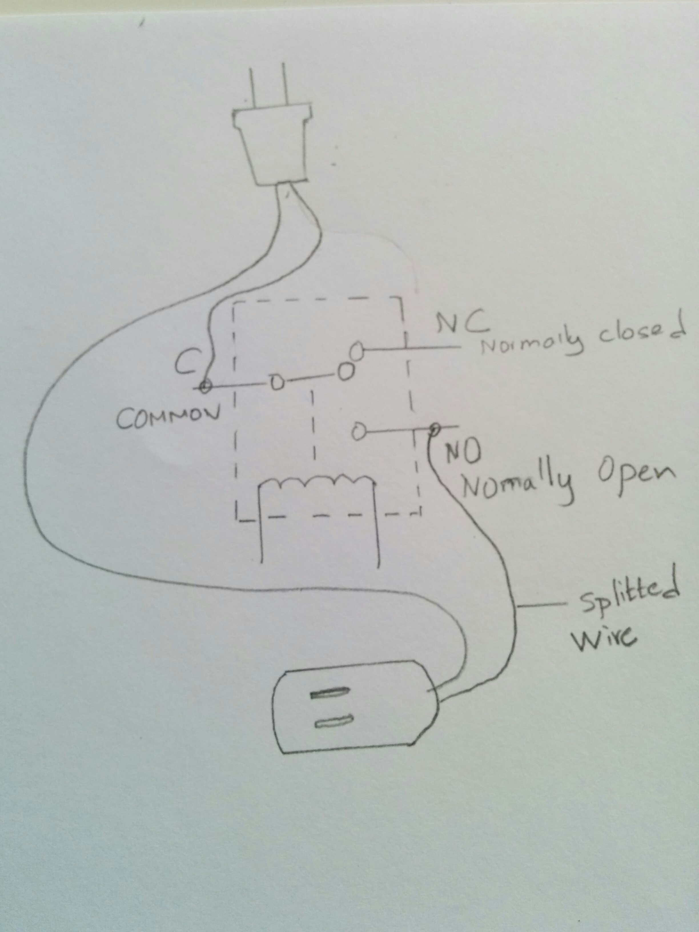
Relays are age old technologies in the field of electronics. It acts as a switch. The input to the relay can be ac voltage (110 to 240 V). Using a microcontroller such as arduino, we can turn the relay on/ off
We are going to connect high voltage to the relay, please respect ac current and take extreme precaution while connecting the wires to relay. This is too dangerous, proceed at your own risk
Instead of directly configuring the relay to the power outlet, I used extension cord. The concept is same though.
In the extension cord, leave one wire as it is and clip the other wire. Connect on end of the wire to Common (C) and the other to NO (Normally Open)
Connect the Relay shield to Arduino, stack the Xbee Shield on top or the relay shield. Plug in the Zigbee configured as Router on the Xbee Shield
I used Xbee Shield to Connect the Xbee to arduino. Make sure that the settings in the shield is set to Xbee. This shield along with arduino can also be used to write the firmware settings when we set the switch to usb. It uses arduino's build in FTDI chip to write the data to Xbee.
Plug in the cords and power up the arduino using external battery source. The receiver is done.
Configuring the Server
To setup up the server we need the Raspberry Pi 2 running on windows 10 IOT and Zigbee set up as coordinator.
Connect the Zigbee to FTDI adapter, and 6 pin FTDI RS 232 USB cable to raspberry pi usb port. We will set up a webserver on the raspberry pi using UWP. The server will wait for user input and based on the selection, it will write the serial data to usb port in which the FTDI RS 232 cable is connected, the Zigbee will transmit this message as radio waves. We have already set up the router's DH and DL in the coordinator Zigbee, so the message is sent to correct Zigbee Router.
To know more about FTDI drivers for raspberry pi please see https://github.com/jark/ftdisample
Please follow this video to setup the server on Raspberry Pi.
All the code samples are available in github.
Enable Azure
To control our home from anywhere in the world, we enable cloud services to our application.
You need to create a website and host it in azure. Create a Azure SQL DB to authenticate/ authorize the users for your site. Create a Azure Cloud Storage Service to take up our commands. Process these commands from Raspberry PI Blinky App and control your home.
You need to refer this article to create storage tables:
https://azure.microsoft.com/en-us/documentation/articles/storage-dotnet-how-to-use-tables/
To create Sql tables, refer this article:
https://azure.microsoft.com/en-us/documentation/articles/sql-database-get-started/
Please watch the video tutorial on how to use azure for our project:
Demo
I tried to show how you can control the power outlets in two ways,
- Accessing the in network raspberry web server url
- Through aspnet5 web application hosted in Azure
Conclusion
- This kind of automation solves many real world problems. By attaching additional sensors like light and motion detector, we can turn on/ off the light or atleast provide the data to user to save energy.
- Elderly people can use remote to control their power outlets. In this case, we need to have additional RFID device.
- We can create schedule to turn light on/ off so that the power can be saved.
- If there are any intruder, all lights can be turned on.
- On a vacation, no need to worry.. we can just shut off our home within a click of a button.
- No need to maintain your room temperature all the time, do it when you feel appropriate. Saves energy.


_ztBMuBhMHo.jpg?auto=compress%2Cformat&w=48&h=48&fit=fill&bg=ffffff)


_3u05Tpwasz.png?auto=compress%2Cformat&w=40&h=40&fit=fillmax&bg=fff&dpr=2)
Comments
Please log in or sign up to comment.