A robot is a programmable machine that can assist or replace human efforts. For example, they can reach hard-to-reach places or be found in industrial applications.
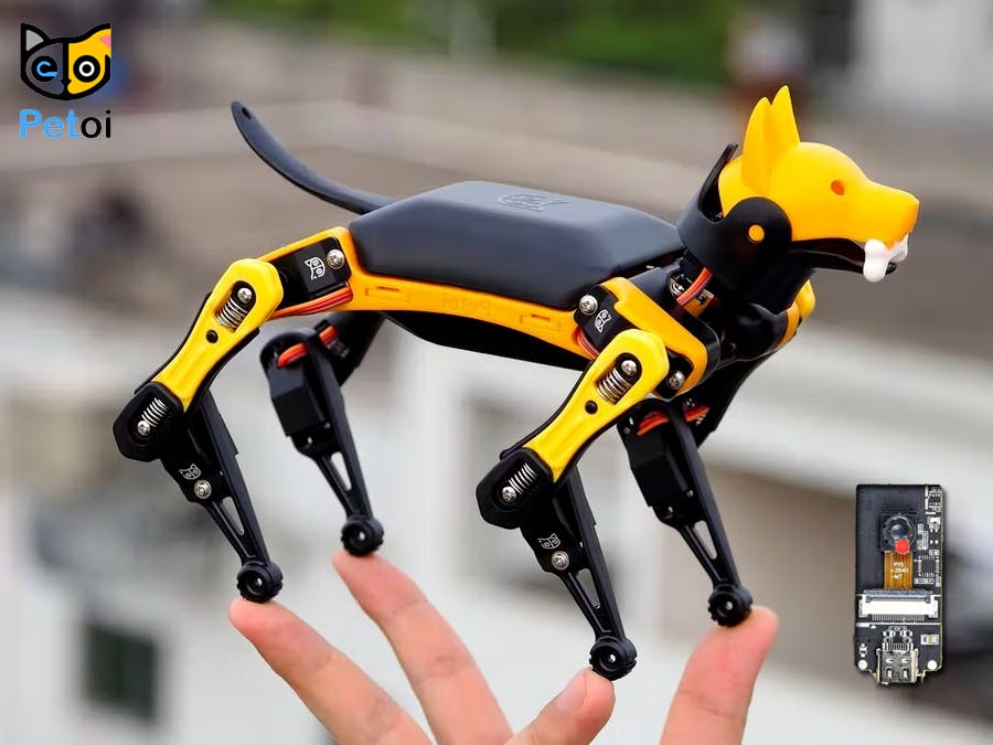
Petoi Bittle is a tiny but powerful robot that can play tricks like real animals. An affordable Boston Dynamics-style quadruped robot dog that makes a perfect tool for learning, teaching, researching, or a surprising gift to impress family and friends.
The goal of the project to provide a dynamics-oriented quadruped for STEM education and research, makers and other tech enthusiasts.
Bittle is the second generation of quadruped robots made by this company, which was made after OpenCat or Nybble. An important feature of this project is that it is completely open source.
This robot is currently sold in three versions:
- Base Kit
- Pre-assembled Kit
- Developer Kit
If you have a challenge to make it from scratch, I suggest you choose Base Kit or Developer Kit, It's like making a puzzle, This Puzzle-like Body Frame with very few screws that on average, it takes about one hour to put together the body from scratch. Also pre-assembled kit robot dog that can be played out of box. In this tutorial, I used an pre-assembled version.
A closer lookIf we want to do a more detailed study, we must say that the different parts of the robot have been designed with special precision and elegance. One of these parts is the servo.
The servos, which is one of the most important parts of this four-legged robot, is made entirely of metal and is made especially for this robot. Their controllable angle is 270 degrees which has an Coreless motor with all-metal gears built into it. In the tests I did myself, I can confirm their strength and endurance. 9 servos are used in this robot, each pair of servos is for one of the legs. A servo is also attached to the neck.
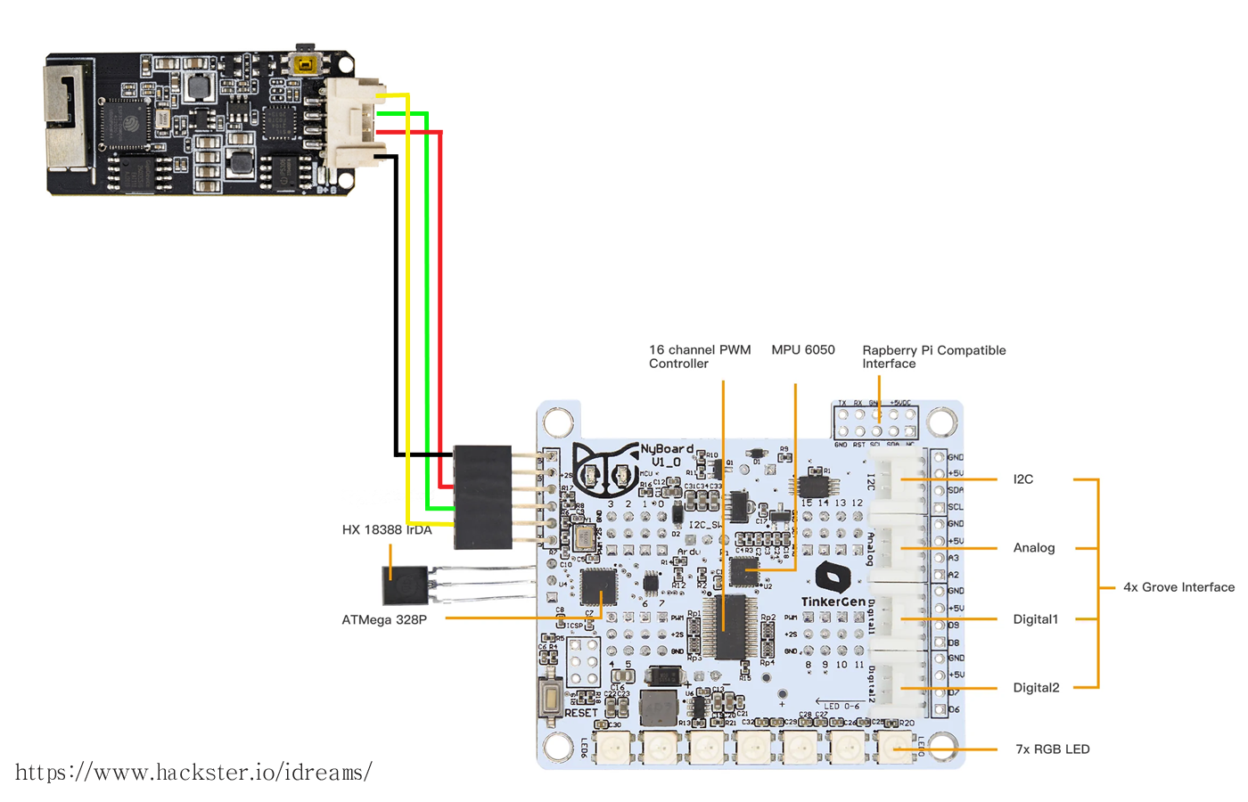
The main control chip, ATMega328P is located under the mainboard, so you won’t be able to see it and the cover needs to be removed. In the center of the board you can see another chip, PCA9685, which is used for controlling the servos. You can think of main control chip as the brain and servo driver chip as a spinal cord in mammals, responsible for motor coordination. Due to the update and iteration of the product, there are Several different versions of the mainboard of the Bittle kit. You can judge which model your Bittle motherboard is based on the silkscreen on the upper left corner of the front of the mainboard. Although ATmega328P looks very simple and powerless on paper, in practice, it works very powerfully, The robot firmware is also very smart and clever. Click +, +, + for more information.
A two-cell Li-ion battery with a capacity of 1000 mA/7.4Wh and an output voltage of 7.4V-5A to power Petoi Bittle for about one hour of continuous walking. This battery is charged with a normal 5V-1A charger. Battery charging time is about 2 hours.
I had Pre-assembled Kit which contained the following contents and by default everything was ready to use. If you have a Base kit or un-assembled version, Don't worry, you can get started with this guide.
It is very important to calibrate it before use. If we don’t calibrate the servos before using (Especially un-assembled versions), they may rotate to any direction, get stuck, cause damage to either the servos or body parts and cause robot limbs not to function properly. Get help from this guide for this purpose. Also, very useful videos on how to assemble the robot have been published by the production team.
Control and play with the BittleThere are three common ways to control a robot:
The most important feature of Bittle is the control through the serial port. This feature makes it possible to control it with a wide range of devices such as Raspberry Pi, Micro:Bit, etc. Bittle abilities can also be added through Grove Connectors and Extensible Modules.
One of the good things about Bittle is that it allows children to program via CodeCraft (scratch-based).
The robot control mechanism is very simple but cleverly designed, so that commands are sent to the robot through the serial port, the robot processes it and behaves accordingly. It is also possible to add custom skills to the Bittle.
For example, the m1 40 command causes servo 1 to move 40 degrees or with the wkL command the robot walks to the left. The development team is always trying to fix the robot bugs, so it is best to update the Bittle firmware every once in a while, this is done via Arduino IDE.
In this section, we will implement a project. As I explained before, various modules and microcontrollers can be connected to Bittle through the serial interface.
The ESP32 Camera (ESP32CAM) module is a good choice for this part of the project due to its reasonable price and having an Grove Connectors. Also, due to having ESP32 core, a wide range of projects such as image processing and artificial intelligence, etc. can be easily done. Of course, keep in mind that you can also use ESP32-CAM AI-Thinker module.
With the help of a 4 pin Male Jumper to Grove 4 pin Conversion Cable, we can easily communicate from the ESP32CAM module to the Bittle board. Make sure the white wire is connected to RX and the yellow wire is connected to TX. Also connect the 5v and GND wires to the 5v and GND, respectively.
Here, I designed a simple, web-based interface to control the robot. Live camera images are sent via Wi-Fi, and user commands are transmitted to Bittle via the serial interface. All control keys can be edited and added.
After turning on the robot, the camera also turns on, a hotspot called Bittle-CAM is created automatically (WiFi password is available in source code), which can be easily run on a mobile phone browser or pc browser without installing a program. Just type the following URL in your browser:
http://192.168.4.1/In addition, a static image will always be visible and usable via the link below:
http://192.168.4.1/image.jpgNote that the quality and size of the received images can be changed through this line.
For easier testing of the robot, a stand with calibration capability has been designed by Petoi Team that can be printed by a 3D printer.
Now that we have been able to give vision to the robot, we can do more projects such as: recognizing faces or different facial expressions and controlling the robot through hand movements, etc. I will try to do this project in the next tutorial.


Comments
Please log in or sign up to comment.