My goal was to build a simple programmable unit to control standard 433MHz switch units. I want to use that to control the lights in our house if we’re not at home. I am not a programmer and used some Turbo Pascal back in the 80's in electronics school. Hooking up an Arduino to a real time clock and copy/pasting code is no problem, but writing code to compare times and dates is way to complicated for me at this moment. Then I discovered Cayenne! On Thursday I received my Wemos D1 and after a few hours of playing around the first version is working.
To get the 433MHz transmitter to work from the Arduino/Wemos D1, I used the following resource to get it to work and used a 433Mhz receiver to discover the code that the manual remote control unit was transmitting: https://arduinodiy.wordpress.com/tag/elro/
To figure out the @#%# pin mapping of the Wemos D1, I have played around with the Arduino and was somewhat confused by the Wemos D1 pin mapping. Check the following page for more information: https://github.com/esp8266/Arduino/blob/master/variants/d1/pins_arduino.h
For this project I used the Wemos D1 pins labelled D9 (=2 in my sketch) and D3 (=5 in my sketch). Took me some time to figure that out.
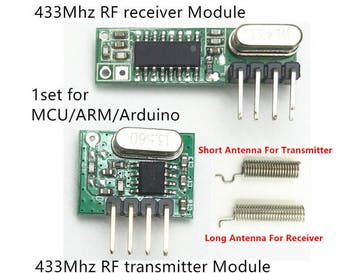
What's ConnectedWemos D1 V2 (includes WiFi, supports most Arduino code but has a weird pin mapping) 433Mhz transmitter Elro 220V switch unit.
Img 0: These are the 433Mhz transmitter and receiver I use.
Img 1: This is basically all it takes, the D1 and the 433Mhz transmitter.
Triggers & AlertsI am not using triggers or alerts (yet).
SchedulingScheduling is one of the two main functionalities. I have built the controller for 1 channel, but can easily add multiple channels by copy/pasting code. One channel can control multiple switch units in parallel.
Dashboard ScreenshotsIt’s a very simple set up at this moment but as said, I can easily add other channels.
Photos of the ProjectImg 1: D1 connected with the orange data wire to the transmitter. I also hooked up an LED to indicate if the switch is supposed to be on or off. (Don't forget to put a 1k ohm resistor in series to ground.)
Img 2: The 433MHz transmitter. It has 4 pins but only the data, + and - are used.
Img 3: The 220V switch unit and the manual remote control unit.
The sketch codecayenne_WemosD1_V2.txt (2.0 KB)
Explanation is embedded in the code.
Issues- I sometimes encountered issues with scheduling. At this moment I am running a duration test and scheduling is working well. The issue I had was that I scheduled an event and it just did not work.
ihatespam


Comments
Please log in or sign up to comment.