-I've seen videos on YouTube of homemade, 3D-printed, Spider-Man masks with movable eyes and I thought it looked pretty cool. I don't have access to a 3D printer and I really did not want to create my own mask. I have already made an Iron Man helmet using Pepakura, resin, bondo, and that was a lot of work. After a trip to the Disney Store, I found a Spider-Man mask with movable eyes that can be controlled using a slider on each side of the mask. I wanted to make it better by adding small servos that can be controlled by a button on the side. Adding a Bluetooth module allowed me to have different modes that can be controlled by a phone.
Here is my mask in action:
Let's get started!
STEP ONE: DisassemblyI don't have any photos before I modified the mask so the following photos will be the modified mask.
Remove the screws:
We will be removing some parts that we don't need here. The circuit board (circled in green), the speaker (circled in yellow), and the switch (circled in purple).
De-solder the circuit board from the battery pack (grey arrow), and de-solder the button (blue arrow) from the circuit board. We will need the button for later.
Use a Dremel tool to cut where the speakers were. We will be mounting our microcontroller circuit board here later and we will be cutting holes here for the servos.
Cut out two holes like in the photo below so that the servos can go through them as shown:
Drill two small holes on each side of the eyes (marked in red) and connect springs (salvaged from pens) to the servo. This allows the servo the control each eye.
Use a hot glue gun or your preferred method to glue the servos in place as shown in the photo above.
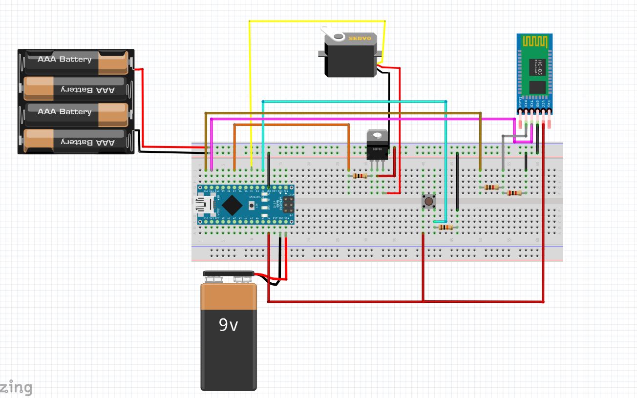
STEP FOUR: ElectronicsWe will be using an Arduino Nano to control the servos powered by the mask's battery pack. The battery pack can power the two servos we will be using and a 9V battery will be used to power the Nano through the VIN pin.
Connect everything as shown in the photo above.
I used two TIP-120 transistors so that we can control the power going to each servos. Without this, the servos will keep running even as it reaches our desired position. Once our servos have reached our desired position (open, close), we can cut power to the servos to save our battery life.
In our code, this is labeled as RightPower and LeftPower. Our signal for the servo position is labeled as righteyepin and lefteyepin.
A 1kΩ ohm resistor is connected to the base of the transistor for protection.
The button in the photo represents the button at the side of the mask.
The Bluetooth Module (HM-17) will be connected to the Arduino as well. The TX pin can be directly connected to the Arduino and the RX pin will need to be connected to a voltage divider as the HM-17 can only take 3.3V for input.
It will be connected like in the photo below:
Modify to your liking and upload the code using the Arduino IDE below.
STEP SIX: Bluetooth ConnectionUsing the RoboRemo app (the paid version can give you more than 5 modules), you can connect to your Bluetooth module without configuration. Pair the bluetooth module with your phone (default password is 123456) and it will show up on the list in the app. You can download the RoboRemo file I have setup for myself and you can modify it to your liking. Add different modes to customize your mask. You can import the interface using the RoboRemo app. The file can be found below.
STEP SEVEN: Done!Connect to the Bluetooth module using the app and everything should be working like in the video!


Comments