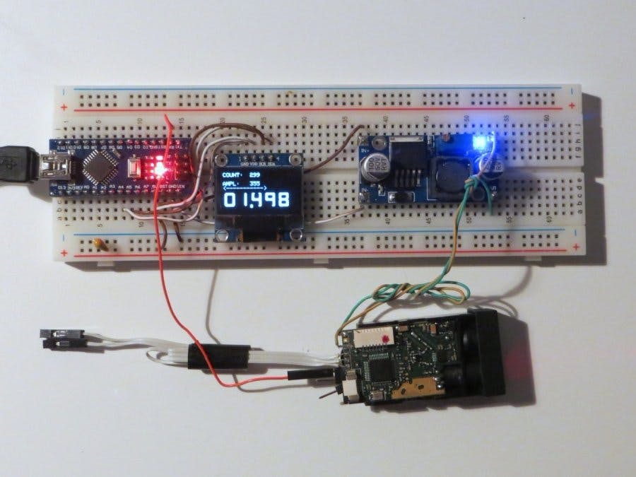
Need fast and cheap laser rangefinder module for your Arduino project?
Of course, you can use specialized modules for this task, but most of them have a big price. VL53L0X/VL53L1X modules are cheap, but they have very large field of view.
So I found a solution: using cheap "X-40" laser tape measure as a laser rangefinder. These devices costs $20 and less and they can measure distance up to 40m with accuracy ~3mm. But there are two problems - there is no way to get readings from the tape and the measurements are slow - less than 1 Hz.
To solve that problems I made reverse engineering of that laser tape measure and write my own firmware for the STM32 MCU of the laser rangefinder module. Measurement speed was important for me and I can reach ~60 Hz, but maximum stable distance decreased to a ~6 m (full maximum range is 37 m, but I did not tested it).
Distance measurement accuracy can vary from 1 mm to 10 mm depending on target colour and distance.
Module dimensions: 25x13x50 mm.
IMPORTANT NOTICE: YOU WILL LOSE ORIGINAL FIRMWARE, SO THE DEVICE CAN NOT BE USED AS A LASER TAPE MEASURE LATER!
Note that "X-40" laser tape measures can have different revisions of the laser rangefinder module, and my firmware supports only some of them!
"X-40" is not the only name for a laser tape measures with such modules - I know that there are exists several different Chinese laser tape measures with suitable modules.
Step 1: Disassembling laser tape measureLet's disassemble laser tape measure to get a laser rangefinder module from it.
You need to unscrew 7 screws from the case:
Disassembled laser tape measure:
You can see small laser rangefinder module inside the case of the device. You need to disconnect ribbon cables from the module and remove module from the case:
Note that module is marked as "701A". My firmware supports only "512A" and "701A" module versions. Several users confirmed that "703A" modules are working too (I did not tested it).
UPD 11/2019:
Attention: It was found that newer "x-40" laser tape measures come with "M88B" modules. Marking is "88B" at the PCB near MCU. That modules are based on STM32F0 MCU (it has QFN-32 package). That modules are not supported by my firmware!
UPD 10/2021:
Attention: added support of U85 modules: see link!
UPD 10/2024:
Attention: added support of B2A modules: see link! They are used in modern types of laser tape measures.
If yours module is supported, you need to unsolder power lines from the module.
Step 2: Programming laser rangefinder moduleYou need to write a specialized firmware to the MCU of the module to get needed functionality.
1. Firstly you need to solder some wires for programming the MCU. Pinout is shown at the picture:
Connect pins 7-8 of the keyboard connector - it is need for power up.
Lines "GND"and "Vbat" must be connected to the power source. Power voltage range is +2.7...+3.3V. There must be +3.5 V at the "Vdd" line when power is supplied to the module.
Lines "GND", "SWDIO", "SWCLK", "NRST" must be connected to the ST-LINK programmer. Line "NRST" is very important - original firmware of the MCU is locked, so this line is needed to enter MCU to programming mode.
Some programmers have this line, and some (cheap) are not, but there is a workaround for this problem.
Also, some programmers (like original "ST-LINK/V2 ") need "Vbat" line to be connected with the "VCC/TVCC" line of the programmer.
Example of connections (this programmer does not have "NRST" line):
2. Install "ST-LINK utility" to the PC. If you don't have experience of using that software, there are a lot of tutorials in the Web.
You need to configure utility (Target -> Settings):
If your programmer have "NRST" output, you can just turn on the power and press "Target -> Connect" at the utility.
If it does not have such line, you need to do that steps:
- Turn on the power.
- Connect "NRST" line of the module to the GND.
- Press "Target -> Connect" at the utility.
- Quickly disconnect "NRST" line from the GND.
- Utility must show the connection
Yon must get such picture:
3. MCU flash is locked for reading, so you need to disable "Read Out Protection". You will lose original firmware at this step!
Open Target -> "Option Bytes" menu. There must be such settings:
Switch "Read Out Protection" to "Disabled" and press "Unselect all" button, than press "Apply" button. Try to restart module (by disconnecting power).
Press Target -> Connect. There must be information about successful connection at the log window and you must see memory contents - filled with 0xFF. Now you can load custom firmware to the MCU.
4. The needed firmware is placed here: https://github.com/iliasam/Laser_tape_reverse_engineering/tree/master/Code/Firmware_dist_calculation_fast
Select suitable HEX file for yours module and download it to the MCU Flash using "ST-LINK utility".
Step 3: Connecting laser rangefinder module to the ArduinoYou need to solder a wire or a some connector to the TX pad at the the board:
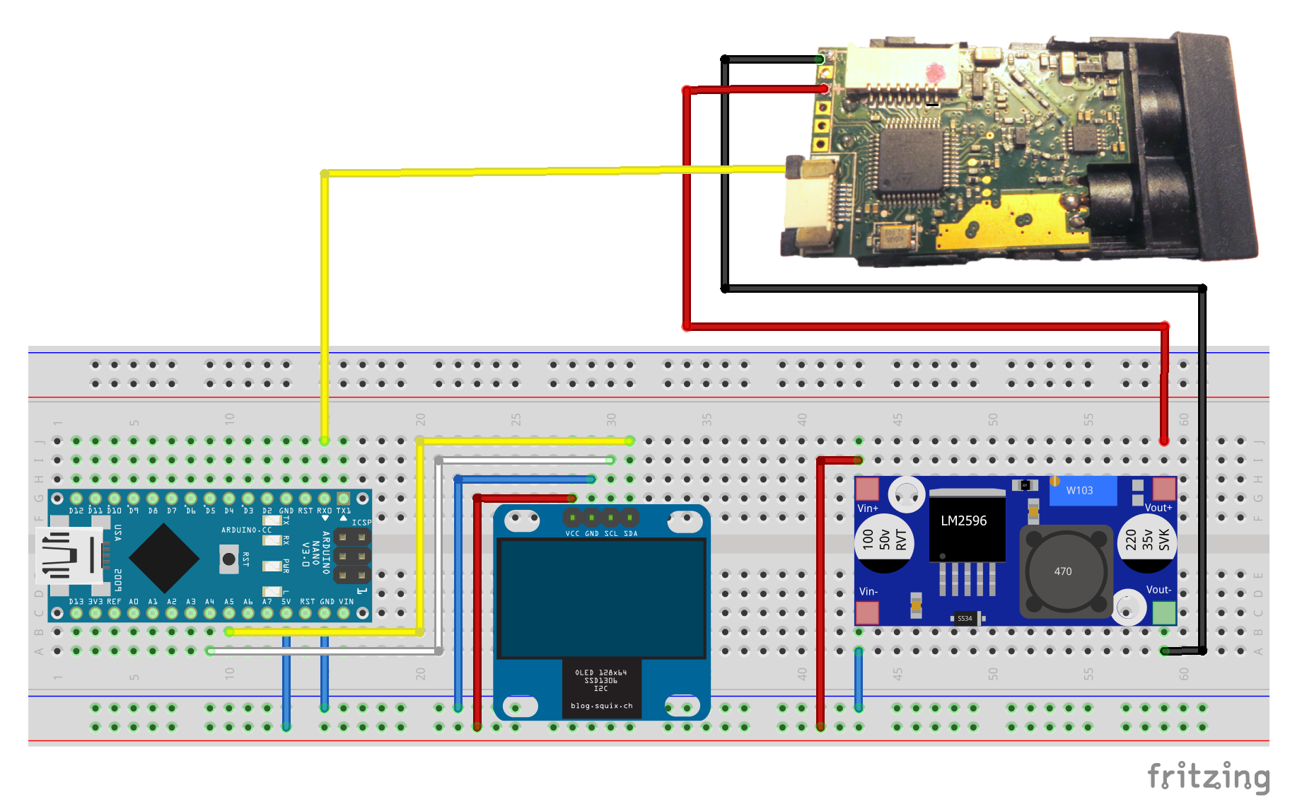
See the connection schematic below.
Firstly, you need to check that rangefinder module is working well. At this step you don't need to connect OLED display to the Arduino - just connect TX line of the laser rangefinder module to the TX line of the Arduino, and power lines of the module to the +3V power source.
Create empty sketch and load it to the Arduino. Open "Serial Monitor" at the Arduino IDE. Select baud rate: 250000
If the rangefinder module is working fine, you will get the same data:
DIST;01937;AMP;0342;TEMP;1223;VOLT;115 DIST;01937;AMP;0343;TEMP;1223;VOLT;115 DIST;01938;AMP;0343;TEMP;1223;VOLT;115 DIST;01938;AMP;0343;TEMP;1223;VOLT;115
In fact, it is better to use specialized USB-UART converter for this test. Select 256000 baudrate in its utility (it is real baudrate of x-40 MCU).
Secondly, you need to assemble full schematic with display.
Connect TX line of the laser rangefinder module to the RX line of the Arduino (you need to disconnect that wire during loading program to the Arduino).
If everything is working fine, you will get the same result:
You can see display with 3 numbers:
- "COUNT" - counter of the received values
- "AMPL" - amplitude of the signal. Symbolic bar ("<--->") below shows amplitude graphically (in logarithmic scale).
- The biggest value - distance in meters and millimetres.
After a first start, laser rangefinder module need to be calibrated.
You need to place some white object at a certain distance from the module. A distance to this object will become a zero distance for the rangefinder module. To start calibration process you need to connect keyboard from the laser tape measure and press lowest button. Module will beep twice - at the start of calibration and at the end (calibration duration is near 10 seconds).
Now you can use this laser rangefinder module.
Links:
1. Github - reverse engineering results and source code.
2. Habr.com - Google translated article about laser tape measure reverse engineering process.
Sorry for my English - I'm from non English speaking country.


Comments
Please log in or sign up to comment.