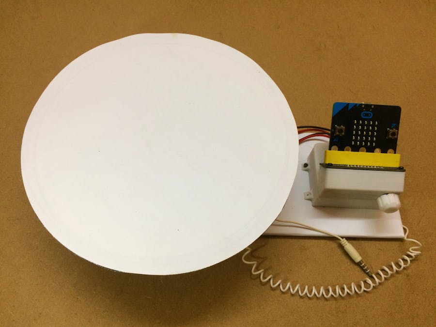
I tried to automate the photographer's turntable, which is used to capture 360 photographs of any product. Generally, the person has to manually orient the object and rotate the turntable and capture the image. But this all process can easily be automated using a stepper motor to control pressie movements, and the angle of the object in front of the camera and the device can also trigger the click of the camera as soon as the position is oriented, which will make the cumbersome task into a fun little experience.
The Stepper MotorThe principle behind controlling any stepper motor with any stepper driver is quite simple. There are primarily two control pins for steps and direction. The direction pin is level control, and the step is edge control, which means to set the direction, the DIR pin is needed to be either pulled high or pulled low. Now to step in the set direction, we will send a complete pulse cycle to the STEP pin.
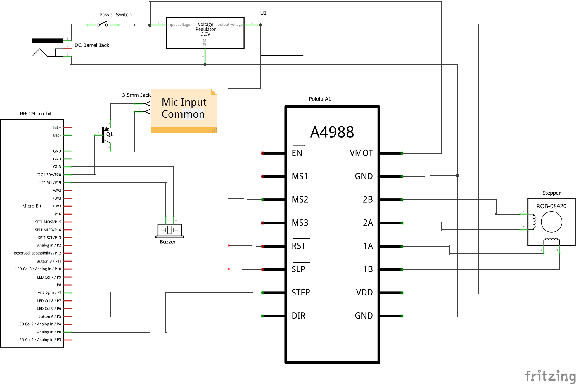
I have utilized the NEMA17 stepper motor, and to control it A4988 stepper driver is used, which allows various stepping options from full step to 1/16 stepping mode.The code is configured for 1/8th stepping mode. It is still easily reconfigurable with the "totalSteps" Integer constant (for full steps mode change it 200, for half steps 400, etc.) and set the stepping mode on MS1-MS2-MS3 pins of the driver according to the table given below.
The smartphone's camera or professional DSLR Camera can be controlled externally to trigger the clicking action. This action's principle is somewhat similar to manual clicking of a logic pulled high momentary push button. To trigger our camera we are going to utilize Mic Input and Common pins of the 3.5mm Jack when we open our camera in the smartphone the Mic Input pin is pulled high which will pull low in order to trigger the action and to do so we are going to utilize a generic PNP Transistor as a switch.
As the current from the Mic input is already controlled by the smartphone so we don't deen any current limiting resistors out in the circuit and the control signal will be pulled low by the Micro bit to trigger the switch.
*Note: I have tested this circuit on my Samsung J8 and it works perfectly
The NRF52 microcontroller on MicroBit is of 3V logic, while we need a 12V supply for the stepper motor so we will utilize a regulator to convert 12v to 3.3v, we can utilize a switching regulator as the voltage difference is high but the current consumption is very low so linear regulator such as AMS11173.3 would work fine for the project.
As we are going to use Micro Bit v1.5, only pins 0, 1, 2, 12, 13, 14, 15, 16, 19, 20 are available among these 0, 1, 2 can be used for analog value reading, as the rest of the pins are utilized by the led matrix controlling.
I have utilized a potentiometer for speed and various user control options such as the number of images, direction and position control, etc.
3D Print (Enclosure & TurnPlate Stepper Coupler)I have attached the 3D Files for printing, the MicroBit adapter mount will be glued on the circuit enclosure, I have separated both of them so as to print without any support.
There are slots for DC Barrel Jack and Power Switch, added from outside after inserting the circuit into the enclosure.
AssemblyFirst, assemble the Microbit attachment part, the potentiometer is added from the back and then orient it according to the slot provided and stick it there using the glue gun. Make sure the potentiometer isn't moving when its knob is rotated.
Then attach this potentiometer/Microbit adapter part to the enclosure part using some super glue.
Now let's make a connector that will connect the Microbit to the circuit, we are going to utilize pin 0, 1, 2, 19, 20 for our connections so connect those pins using female 2.54" pitch headers.
Now it's time to make few final connections after the circuit is placed inside the enclosure. Connections for the potentiometer, and stepper motor, you can also choose to use wago or JST type connectors for stepper motor in case you want to change them back later.Then connect the female header cable to the micro bit adapter and tighten the screws to secure the adapter to the enclosure.
Solder the switch and insert in the given slot, these switches are snap-fit. It will remain fix in its slot automatically. Make sure to add some heat shrink insulation to the connections.
To make a turn plate use some plywood or 4-5mm plastic sheet cut into a circle of 20-25cm diameter and attach the coupler to it using some 2mm screws. Then it will be friction fit on the stepper motor's circular shaft.
Complete the assembly by connecting the stepper wires and fixing the enclosure and stepper motor on a board.
The Code
with MicroBit.IOs;
with MicroBit.Buttons; use MicroBit.Buttons;
with MicroBit.Display;
with MicroBit.Time;
with HAL;

procedure Main is
   --mod_Int is a data type with range 0,1 and further numbers will be modulus by 2
   type mod_Int is mod 2;

   stepPin : constant MicroBit.IOs.Pin_Id := 0;
   dirPin : constant MicroBit.IOs.Pin_Id := 1;
   potPin : constant MicroBit.IOs.Pin_Id := 2;
   buzzPin : constant MicroBit.IOs.Pin_Id := 19;
   cameraTriggerPin : constant MicroBit.IOs.Pin_Id := 20;
   potValue : MicroBit.IOs.Analog_Value := 0;
   lastPotValue : MicroBit.IOs.Analog_Value := 0;
   steps : Integer;
   imgNum : Integer ;
   mode : mod_Int := 0 ;

   --totalSteps : constant Integer := 200; --in full stpes stepping mode
   --totalSteps : constant Integer := 400; --in half steps stepping mode
   totalSteps : constant Integer := 800; --in quater steps stepping mode;
   --totalSteps : constant Integer := 1600; --in 1/8th steps stepping mode
   --totalSteps : constant Integer := 3200; --in 1/16th steps stepping mode


   procedure moveSteps(stp : Integer) is
      d : Integer := 25;
   begin
      if stp<0 then
         MicroBit.IOs.Set(dirPin,True);
      else
         MicroBit.IOs.Set(dirPin,False);
      end if;

      if abs(stp) <= 41 then
         for i in 1..abs(stp/2) loop
            MicroBit.IOs.Set(stepPin,False);
            MicroBit.Time.Delay_Ms (1);
            MicroBit.IOs.Set(stepPin,True);
            MicroBit.Time.Delay_Ms (HAL.UInt64(d));
            d := d-1;
         end loop;
         for i in 1..abs(stp/2) loop
            MicroBit.IOs.Set(stepPin,False);
            MicroBit.Time.Delay_Ms (1);
            MicroBit.IOs.Set(stepPin,True);
            MicroBit.Time.Delay_Ms (HAL.UInt64(d));
            d := d+1;
         end loop;
      else
         for i in 1..20 loop
            MicroBit.IOs.Set(stepPin,False);
            MicroBit.Time.Delay_Ms (1);
            MicroBit.IOs.Set(stepPin,True);
            MicroBit.Time.Delay_Ms (HAL.UInt64(d));
            d := d-1;
         end loop;

         for i in 1..abs(stp)-40 loop
            MicroBit.IOs.Set(stepPin,False);
            MicroBit.Time.Delay_Ms (1);
            MicroBit.IOs.Set(stepPin,True);
            MicroBit.Time.Delay_Ms (HAL.UInt64(d));
         end loop;

         for i in 1..20 loop
            MicroBit.IOs.Set(stepPin,False);
            MicroBit.Time.Delay_Ms (1);
            MicroBit.IOs.Set(stepPin,True);
            MicroBit.Time.Delay_Ms (HAL.UInt64(d));
            d := d+1;
         end loop;
      end if;
   end moveSteps;


   procedure moveSteps_2(stp : Integer) is
   begin
      if stp<0 then
         MicroBit.IOs.Set(dirPin,True);
      else
         MicroBit.IOs.Set(dirPin,False);
      end if;
      for i in 1..abs(stp) loop
            MicroBit.IOs.Set(stepPin,False);
            MicroBit.Time.Delay_Ms (1);
            MicroBit.IOs.Set(stepPin,True);
            MicroBit.Time.Delay_Ms (15);
      end loop;
   end moveSteps_2;


   procedure buzz(i : Integer) is
   begin
      for m in 1..i loop
         MicroBit.IOs.Set(buzzPin,True);
         MicroBit.Time.Delay_Ms (100);
         MicroBit.IOs.Set(buzzPin,False);
         MicroBit.Time.Delay_Ms (100);
      end loop;
   end buzz;

   procedure click is
   begin
      MicroBit.IOs.Set(cameraTriggerPin,False);
      MicroBit.Time.Delay_Ms (150);
      MicroBit.IOs.Set(cameraTriggerPin,True);
      MicroBit.Time.Delay_Ms (2000);
   end click;

   function minMax (num : Integer; min: Integer ; max : Integer) return Integer is
      x : Integer := num;
   begin
      if num < min then
         x := min;
      elsif num > max then
         x := max;
      end if;
      return x;
   end minMax;

   function map (num : Integer; fromMin : Integer ; fromMax : Integer ; toMin : Integer ; toMax : Integer)
                 return Integer is
   x : Integer;
   begin
      x := Integer(Float(toMax - toMin)/Float(fromMax-fromMin) * Float(num - fromMin) + Float(toMin));
      return x;
   end map;

begin
   --initial pin configuraitons
   MicroBit.IOs.Set(cameraTriggerPin,True);
   MicroBit.IOs.Set(stepPin,False);
   MicroBit.IOs.Set(dirPin,False);

   --starting buzzer tone
   buzz(2);

   --main loop
   loop
      --change modes
      if MicroBit.Buttons.State (Button_A) = Pressed then
         buzz(1);
         mode := mode+1;
         if mode = 0 then
            MicroBit.Display.Display('A');
            MicroBit.Time.Delay_Ms (1000);
            MicroBit.Display.Clear;
         elsif mode = 1 then
            MicroBit.Display.Display('B');
            MicroBit.Time.Delay_Ms (1000);
            MicroBit.Display.Clear;
         end if;

         --wait while the button is release to move forward
         while MicroBit.Buttons.State (Button_A) = Pressed loop
            null;
         end loop;
      end if;

      --running the mode
      if MicroBit.Buttons.State (Button_B) = Pressed then
         potValue := MicroBit.IOs.Analog(potPin);
         case mode is
            -- Number of Images selected by potentiometer
            when 0 =>
               -- number of images taken will be in between 5 to 50
               imgNum := map(Integer(potValue), 0, 1023,1,10) * 5;
               buzz(1);
               for i in 1..imgNum loop
                  moveSteps(totalSteps/imgNum);
                  MicroBit.Time.Delay_Ms (1000);
                  click;
               end loop;


               -- Manual changing the position of the turn table, running in main code
               -- here we only click the image when button is pressed
            when 1=>
               buzz(1);
               click;
         end case;
      end if;

      --if mode is 1 then this block will run in every loop to find difference between the potentiometer values and rotate the turn table accordingly
      if mode = 1 then
         potValue := MicroBit.IOs.Analog(potPin);
         steps := map(Integer(Integer(lastPotValue) - Integer(potValue)), 0 , 1023, 0, totalSteps);
         --steps := (Integer(lastPotValue) - Integer(potValue));
         if(abs(steps) > 40 ) then
            lastPotValue := potValue;
            moveSteps_2(steps);
         end if;
         --  MicroBit.Time.Delay_Ms(50);
      end if;

   end loop;
end Main;
The code is primarily is split into two sections of button control Button_A and Button_B pressing, where button A is used to switch between modes, and Button B is used to run that mode.
There are two modes A and B. In mode A we set the number of images we are going to click in 360 degrees, then click button B to start the process. Mode B is to provide precise manual control of the turntable with the potentiometer position and then button B to click the image.
Apart from that, there are two procedures for stepping control: direct stepping and the other with a crude acceleration curve. Basically, it will start stepping slow and reach a particular speed and stay for that speed and then deaccelerate to stop.
stepPin, dirPin, buzzPin, cameraTriggerPin all are constant MicroBit.IOs.Pin_Id and can be configured to whatever pin you may desire.If you have configured the stepper motor driver in a different stepping mode, then uncomment that from the code.
Along with stepper control procedures, there are some procedures for mapping the integer from a given range to a different range, camera clicking and buzzing a buzzer.
Programming the Micro:BitTo program the Micro:Bit you need the AdaCore's Micro:Bit Library from the link given below. Then go to its examples>MicroBit and create or duplicate a project there. If you are going to create a new project from GNAT Studio then make sure to add the Micro:Bit library as a dependency to the project
Dependencies can be added from Edit>Project Properties>Dependencies.
The dependency you need can be found in the repo > board > Microbit.
After adding the dependency you can move forward to write your code where GNAT Studio helps a lot in writing codes quickly by suggestions, auto-filling, library referencing, etc.
After writing your code to compile it just click the hammer icon above to build the project. To upload your code click the "Flash to Board" button in the same menu row.
ExamplesTo take a camera stand or selfie stick (or just clamp the selfie stick to bench wise as I did 😜) stand and orient the camera to focus on the turn plate and lock the focus and exposure on the object, and click button B to start the process.
It will be better if your zoom the camera to the turnplate so only the white area is visible.
Video/GIFs from ImagesAfter you have taken the desired number of images to create gifs from it you can use any android app like GIF Maker or open-source software like GIMP, or online software like ezgif.comSimply import all the images as layers from the file menu then export as GIF (select as Animation).


_9nsOFQ7ama.png?auto=compress%2Cformat&w=48&h=48&fit=fill&bg=ffffff)


_IHYK2AHej1.png?auto=compress%2Cformat&w=40&h=40&fit=fillmax&bg=fff&dpr=2)


Comments
Please log in or sign up to comment.