


Hardware components | ||||||
 |
| × | 1 | |||
 |
| × | 1 | |||
Software apps and online services | ||||||
 |
| |||||
| ||||||
| ||||||
Hand tools and fabrication machines | ||||||
_LWNORVejBN.png?auto=compress%2Cformat&w=48&h=48&fit=fill&bg=ffffff) |
| |||||
Remanent memory expansion for Arduinos with GigaDevice NOR flash
Adding remanent memory allows variables and measurements to be persisted even when the Arduino loses power. Interfacing a GigaDevice GD25 flash chip to the Grove module form factor provided a few interesting challenges.
StoryWhile most modern microcontrollers do have some kind of write-back capability, their usage often leads to stalls in program execution. This is caused by optimisations in modern memory architectures where program flash is also used to hold remanent memory constants.
Using an external SPI NOR-Flash chip lets you work around this problem. In the following steps, we will use a GigaDevice GD25Q16ESIG. Its pinout presents itself as shown in the image.
Figure. 1.png
Modern SPI flash memory is able to work at extremely high speeds. This high speeds are not only achieved by bobbling the clock line quickly - up to four data lines can be used to transfer multiple bits at the same time.
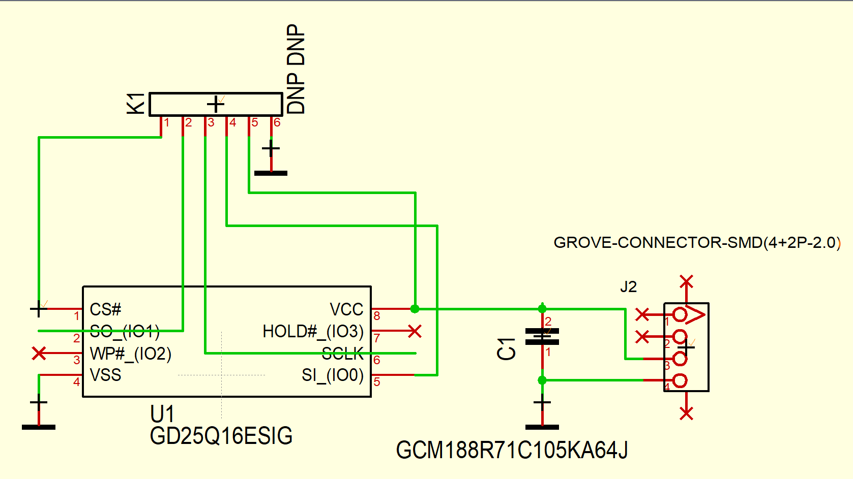
Due to the relative simplicity of the Arduino project, we will, however, limit ourselves to using but one line. This then leads to the schematic shown in the figure.
Figure. 2.png
The Grove module standard is one of the most vibrant development-board form factors on the market. Seeed Studio provide an excellent overview of products at https://www.seeedstudio.com/category/Grove-c-1003.html. Even though the Grove form factor is highly flexible, in practice their use of only four pins makes transmitting SPI signals over the Grove connector difficult. This problem was solved by adding additional pins as shown in the figure.
Figure. 3.png
DuPont pins with a 2.54 mm (0.1 inch) pitch are commonly available, and usually also made with various connector types. This way, the user of the module is given flexibility in how he wants to leads the SPI signals from his microcontroller to the GigaDevice board.
Seeed Studio generously sponsored the production of the series units. In order to prevent wasted costs, a local PCB company was instructed to do a first shot. This shot was then soldered by hand in the lab. The strange placement of the connector became necessary because the surface mount and the through-hole connectors have inverted pinouts.
Figure. 4
When the job was verified to be working, the actual module was uploaded to the Seeed fusion service. Yours Truly wants to emphasise the advanced capabilities of the Gerber checker, with which we are able to automatically match most of the parts. When done, the modules were delivered. An acceptance test was performed after receipt, and the modules worked perfectly.
Wiring to an Arduino DueCreating the actual technology demonstration required the use of a 3.3 Volt Arduino - the Arduino Due has a wide complement of peripherals, and was thus the ideal choice for the following steps. Connecting the board was simple - we simply soldered in a few DuPont pins.
Next, the actual bus interface hadto be declared – for SPI, the main pins are specified. Given that the Arduino platform does not really specify which pin is to be used for chip select, the circuit designer can - usually - select a GPIO pin of his own taste. Yours truly picked GPIO2.
Keep in mind that the CS signal - usually - is relatively uncritical. Usually, not too many SPI peripherals are driven at the same time, which is why the switching frequency seen on the CS signal is much lower than the one seen on the other signals.
How to use it?Download and install the SPIMemorylibrary into your Arduino IDE. Next, include the library and inform the SPIFlash object that GPIO pin two is to be used for the chip select function:
#include<SPIMemory.h>

SPIFlash myIF(2);
Be that as it may, flash memory is - by and large - governed by the JEDEC industry standard. Reading out some of the JEDEC-specified attributes thus makes for a great first test to establish whether the communication between the Arduino Due and the XXX works well.
For this, a library-provided method can be extracted from the sample code - simply place the following snippet in your sketch:
bool getID() {
	uint32_t JEDEC = myIF.getJEDECID();
	if (!JEDEC) {
		Serial.println("No comms. Check wiring. Is chip supported? If unable to fix, raise an issue on Github");
		return false;
	}
	else {
		Serial.print("JEDEC ID: 0x");
		Serial.println(JEDEC, HEX);
		Serial.print("Man ID: 0x");
		Serial.println(uint8_t(JEDEC >> 16), HEX);
		Serial.print("Memory ID: 0x");
		Serial.println(uint8_t(JEDEC >> 8), HEX);
		Serial.print("Capacity: ");
		Serial.println(myIF.getCapacity());
		Serial.print("Max Pages: ");
		Serial.println(myIF.getMaxPage());
	}
	return true;
}
With this out of the way, a test routine can be constructed as follows:
void setup() {
	while (!Serial);
	Serial.begin(9600);
	delay(500);

	Serial.println("Starting up ");
	myIF.begin(MB(16));
	Serial.println("Performing discovery ");
	getID();
}
Passing in the parameter MB(16)to the begin function is required as the libraries author - obviously - cannot put the capacity data of every chip available on the market into his product. By passing in MB(16), we inform the system about the size of the attached chip.
At this point in time, the test harness can be run for the first time. When tested against the chip found on the Grove module, the following result shows up:
JEDEC ID: 0xC84015
Man ID: 0xC8
Memory ID: 0x40
Capacity: 2097152
Max Pages: 8192
Char test write 0Now that successful communication with the flash chip has been established, we can proceed to actually interact with the memory. For that, the following test method shall be used:
void charTest() {
  uint32_t addr;
  int8_t _data, _d;
  _d = -255;
  addr = random(0, 0xFFFFF);
Its first act is the determining of a random address in the memory space. After that, we write information to the chip:
Serial.print ("Char test write ");
 myIF.eraseSector(addr);
  Serial.println( myIF.writeChar(addr, _d, true));
  delay(100);
Serial.println(myIF.error(true));
 Serial.println ("Char test write done");
Flash memory wants to have its sectors erased before new information can be written to them - this is most easily accomplished by invoking the method myIF.eraseSector.
After that, a bit of code is needed to perform a read-back test:
  _data = myIF.readChar(addr);
  Serial.print ("Char test did");
  if (_data == _d) {
     Serial.println ("PASS");
  }
  else {
     Serial.println ("FAIL");
  }
}
Running the program in the current state then, yields the following output:
Char test write 1
Function executed successfully
0
Char test write done
Want to prepPTR Arithmetic doneThis is NOT a string!Char test didPASS
At this point in time, the reader is - by and large - free to explore on his own. More advanced programming examples can be found under the URL https://github.com/Marzogh/SPIMemory/tree/master/examples.
Additional content: a video!Discussing printed circuit-board design is best done in a video. Should you want to learn more about the thought process behind the design, look at the YouTube video below.
Tech supportShould you have any open questions about this flash module, or about the GigaDevice flash-memory product line in general, feel free to contact me at any time via the email address tamhan@tamoggemon.com.
Tamoggemon Holding k.s. also has a competence centre for GigaDevice microcontrollers, including open-source core-based GD32VF. Should you have any questions about that, also contact us via the e-mail address above.
ConclusionThe usage of the GD25Q16 memory chip provided a quick and effective way to add remanent storage to our Arduino. Due to the generous memory capacity, this can be used to store measurement data which can later on be read out.
CreditsThis board creation was part of my entry to the SeeedStudio Grove Module design campaign. Let me, once again, express my gratitude to both GigaDevice and Seeed Studio for providing the hardware required and for all the technical support and friendship!
Should anyone of you feel like creating your own Grove sensor peripheral, consult the documentation found at https://www.seeedstudio.com/blog/2022/07/15/ignite-your-passion-fire-your-thoughts-develop-your-grove-sensor-with-seeed-fusion-for-a-chance-to-win-over-300usd-cash-prize%EF%BF%BC/. Finally, keep the Fusion PCB assembly service in mind - it can be found at https://www.seeedstudio.com/fusion.html .
REFS
https://www.hackster.io/fgsensors/grove-ultra-sensitive-magnetometer-aurora-sensor-b00b0d
https://www.hackster.io/mcmchris/grove-ac-voltage-sensor-for-a-diy-smart-energy-meter-4ae125


Comments
Please log in or sign up to comment.