


Hardware components | ||||||
| × | 1 | ||||
Software apps and online services | ||||||
 |
| |||||
As a beginner you get to your limits quickly after the first project attempts: many ideas are in the head and look for a solution. You ask yourself which sensor is now the right one for the next project? An overview of the sensors often available in sets includes an idea of their ability to have options, limits, and areas of application.
This article describes the first attempts with the sensors printed on black PCB from an Elegoo set. Check fourth and fifth column:
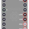
The schematics and the code can be used again and displays the determined values in the serial monitor half-secondly.
Uses A0 as a signal PIN, (+) to 5V, GND (-) to GND. You can also use a digital port: but then returns as a response only the state without individual value.
Here we go: I cant test the IR Receiver and IR Emission-Module, because it is necessary to have a sender and receiver device. It should be possible to mix different devices like Particle Photons, ESP and Arduino, but I found it not exciting and went directly to the next sensor:
A) The Tilt switch (Lesson 5)The tilt switch reminded me of my youth years, where the ball had to be held at the flipper tables to collect points. Frequently, the player pushed his body against the flipper to give the ball the last drive. This was forbidden and was registered at that time by a tilt switch. The measured values could be adjusted and influenced by a slight vibration on the table.
A frequently used component to trigger states. The code used here contains the pull-up "keep the state" without having pressed the button all the time, comparable to the switching on of a lamp.
Please pay attention to the wiring: within the manual it will be shown. You can also neglect and link the guide as shown in the sketch.
int ledPin = 13;
int buttonApin = 9; // VCC 5V goes to D9
int buttonBpin = 8;
byte leds = 0;
void setup()
{
 pinMode(ledPin, OUTPUT);
 pinMode(buttonApin, INPUT_PULLUP);
 pinMode(buttonBpin, INPUT_PULLUP);
}
void loop()
{
 if (digitalRead(buttonApin) == LOW)
 {
   digitalWrite(ledPin, HIGH);
 }
 if (digitalRead(buttonBpin) == LOW)
 {
   digitalWrite(ledPin, LOW);
 }
}
Here I also briefly consider the photoresistor takes the quantity of light supplied to it by means of analog values and can be used directly without resistance.
D) Temperature - 18B20 TempThe analog readings are actually out in the serial monitor, but there is neither a library nor an example sketch and so the user is left to rely on the measured values Fahrenheit or Celsius.
int  sensorPin  =  A0;     // select the input pin for the sensor
int  sensorValue =  0;     // variable to  store  the value  coming  from  the sensor
// Range 0 = to 1023
void setup()
{
Serial.begin(9600);
}
void loop()
{
 sensorValue = analogRead(sensorPin);
 Serial.println(sensorValue);
 // Conversion of the analog value according to data sheet according to Fahrenheit or Celsius
 delay(500);
}
The difference between the 18B20 and DHT11 and the Temp-Sensor within the DS-3213 RTC module is not explained in the manual. Please refer to the relevant data sheet.
On top read the symbols:
G = GND, R = +5V DC and Y = Signal = A0
In various Youtube videos, this module is not only reacting to knocking (for example, on the tabletop - which I donate, since the sensor is only covered by plastic), but also light incident. The higher the weight of the impact, the higher the measured value (within the range 0-1023).
Even if the picture on top the photo interrupter is shown together with the tap module, it is nevertheless two individual components, which can be used independently of each other.
F) Photo Interrupter (Lesson 10)I also end this article with a highlight for me: may I introduce you to the photointerrupter? In our mini-version, it reacts to an external object (in my example a screwdriver): as soon as it is guided between two tiny elevations of the sensor, the trigger closes and the sensor triggers a reaction.
I think of a barrier to determine whether it is closed or open.
I hope that I could give an impression of well packaged and in a transparent box with subdivision including example codes (similar to my attached) and libraries. Here you can find part 1 with the first test of 7 additional sensors. In addition, you will find more beginner projects under my account.
Here is my Paypal link, if you need help in any case.


Comments
Please log in or sign up to comment.