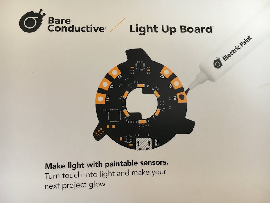
In earlier articles, I had already presented to you the full kit and kept to the specification of the blueprint to put one of the lamp templates into operation. This is still in a nice black picture frame on my desk. Fortunately, the Light Up Board - the electronic engine - is also available for purchase individually. So today I would like to refresh you briefly the basics for commissioning and inaugurate you in one of the secrets to this device. More on that later.
BasicsThe device is not in the usual plastic packaging, but comes in a pretty folder therefore on the back instructions for commissioning will be described.
Also take note of the fact that the small parts do not fall into the hands of children between 0-3 years.
The PIN assignment of the 6 generously designed contacts is also documented. Crocodile clips can be attached here, with conductive paint or, in the use of the holes, also conductive yarns can be passed through.
With the pre-flashed code we can follow the first steps on the back of the cover and are ready to tinkering after a few moments of the boot process.
Did you notice when looking through the pictures that there are more 2x3 PINs available; small and inconspicuous on the left side of the board? Only the imprint on the silkscreen lets us assume that we can communicate with the board. On closer inspection, there are also RXD and TXD ports on the bottom...
SecretsSo what if we could communicate with the board via a terminal program (Termite, Putty or TeraTerm)? Are AT commands allowed - would the board contact you?
The connection was quickly established between PC with termite, a USB2Serial converter to the board and so I could actually establish a connection to the board, but this was just acknowledged with an OK. Upon request to Bare Conductive was then communicated that a communication with the "the board is not programmed to respond to any serial command."
But which way is there then and what are the 2x3 PINs ICSP needed? Unfortunately, a standard USBtinyISP adapter does not fit the 6other ICSP ports. This also fails.
Also, the nice support of Bare Conductive has explained to me, which I would not want to withhold from you:
a.) First of all you will find the schematic of the Light Up Board, the original firmware as INO-File and also Eagle-Icons in case you want to install the Light Up Board in your circuit.
https://github.com/BareConductive/light_up_board_files
b.) The sketch running on the board normally does not interface with the serial port, but the bootloader does - just like on most older Arduinos. If you take a look at this repo and particularly this schematic you can see how this works. Effectively you need an FTDI USB to UART cable (must be a 3.3V version, not 5V!) and wire TX on the cable to RXD on the board, RX on the cable to TXD on the board and DTR to DTR on the board (which is actually cap-coupled). Then, when you upload via the USB Serial port related to the FTDI cable from the Arduino IDE, it pulls DTR low, causing are set pulse, forcing the board to run the bootloader and so uploads the code.
Alternatively, users can upload their own code via the exposed ICSP port on a 1.27mm pitch header.
I am currently employed professionally and I do not have the time to follow these steps. Please give feedback and report which creative projects you have implemented with this Light Up Board!
If you are still looking for a beginner's kit to try Electric Paint with your kids, feel free to take a look at this project description.


Comments
Please log in or sign up to comment.