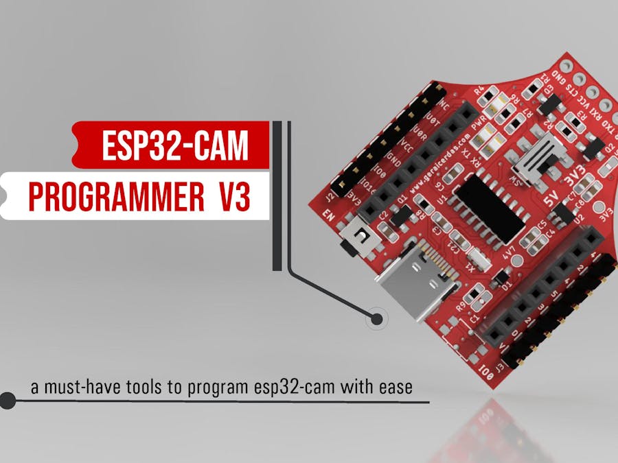
ESP32-Cam is a compact size and low cost ESP32 Development board with OV2640 camera. There's no USB programming port, so you need external programmer like FTDI, CH340 or CP2102 to upload code through serial pins (UOR and UOT).
While it is extremely popular, the ESP32-Cam has several issues. One of common issues of this development board is mostly failed to upload the code. The Arduino IDE will tell you that it "Failed to connect to ESP32: Timed out waiting for packet header". You have to check the wiring between ESP32-Cam and the FTDI as image shown above.
And you know, we have to make sure GPIO0 is connected to GND and then press RST button if we want to enter the flashing mode. After that, we disconnect GPIO0 from GND to enter running mode. We need to do this sequence everytime we upload the code. This is a bit tricky. Isn't it?
Inspiration : Bitluni's Cam-ProgSome of makers Matthias "bitluni" Balwierz already have a solution for this issue. He created an-ons module for easily programming the ESP32-Cam called Cam-Prog. Please refer his blog for the details, https://bitluni.net/camprog, or you can purchase it $12.00 from Tindie https://www.tindie.com/products/bitluni/cam-prog/
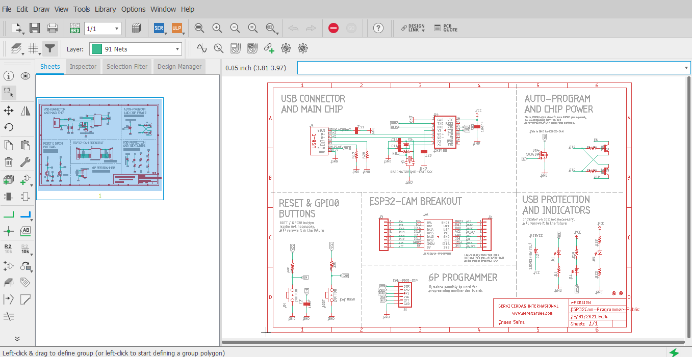
So here I decided to follow his solution as explained in his Youtube channel with some modifications. There are two main parts of the schematic. First, is a common auto-program for ESP32 / ESP2866 which is control GPIO0 and RESET of ESP32. And second, is a N-Channel MOSFET to turn-on and off the ESP32 for replacing the function of RESET, since the developer forgot to breakout the RESET pin.
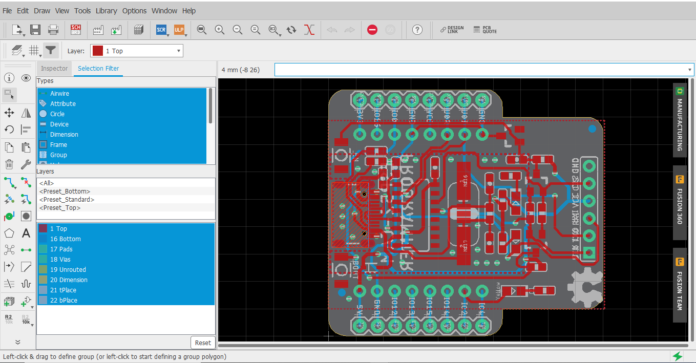
Schematic and PCB LayoutHere is the schematic and PCB layout. You can download the resources on my github. Please take a look here. I use CH340 same as Bitluni's Cam Prog chip. Because this chip is the cheapest serial converter and easy to get here in my country. No need crystal or resonator if you use CH340C. And if you use CH340G you should add 12Mhz Cystall with a couple of 10pF caps or just adding 12Mhz Resonator.
For the USB connector, I use USB type C which is the future of USB connector. I also add a breakout of ESP32-Cam, so you can easly access the pins without needed any breadboard. Or simply you can solder any sensors to this breakout.
In the Board Layout you can push your design to Fusion 360, so you can render the 3D model of the PCB. If you need that please go to this grabcad link to dowload the model.
PCB Manufacturing and Bill of MaterialsYou can download the production file of this PCB design in my github, or just click this link. Simply send the gerber file to your pcb manufacturer like pcbway, jlcpcb, or other local pcb manufacturers.
And here is list Bill of Materials :
- 2x Female Header 8P 2.54mm pitch
- 2x Male Header 8P 2.54mm pitch
- 1x USB type C Connector 16P
- 1x CH340G
- 1x Chip Resistor 1M 0603
- 2x Chip Resistor 1K 0603
- 2x Chip Resistor 330 0603
- 2x Chip Resistor 5K1 0603
- 2x Chip Capacitor 10pF 0603
- 2x Chip Capacitor 100nF 0603
- 1x Chip Capacitor 10nF 0603
- 1x Chip Capacitor 10uF 0603
- 1x N-Channel MOSFET AO3400
- 2x Transistor S8050
- 2x Tactile Switch 3x4x2.5mm
- 3x SMD LED 0805
- 1x Schottky Diode 1N5819HW
All of this bill of materials will cost around USD 2.00 (exluding the PCB)
Assembly All ComponentsNow, it's time to cook :) Prepare your soldering iron, solder wire (0.3mm), tweezer, and don't forget the magical things "flux". And of course the cleaning kit such as, Isoprophyl Alcohol and Kimwipes. You can also use solder paste and hot air solder to complete this task. This tutorial not cover details things about this step. Most of components are 0603 package, so it's able to solder by hand. For the tips, start soldering :
- Chip CH340
- All 0603 Resistors, Capacitors and 0804 LED's
- SMD diode and Transistors
- SMD Crystal
- Push Buttons
- USB C Connector
- Last, male and female headers
References :
https://github.com/geraicerdas/ESP32-Cam-Programmer
https://grabcad.com/library/esp32-cam-programmer-1
Updates : May 08, 2022
In this latest version of this board, I made several changes :
- Added voltage selector switch (5V or 3.3V compatible)
- Added 3.3V voltage regulator
- Change PCB shape and color


Comments
Please log in or sign up to comment.