Digital to Analog Converter (DAC) is a system that converts digital signal to its corresponding analog signal. Vice versa, Analog to Digital Converter (ADC) is a system that converts analog signal into digital ones. There are many applications of DAC such as audio, video, mechanical, and communication purposes. Most of its use is for audio. The suitability of a DAC is determined by its parameters some of which are resolution and sampling frequency, There are several architectures of DAC. In this project, I'll explain the R-2R Ladder (Resistor to 2 Resistor Ladder) DAC.
The R-2R Ladder- The Theory
The R-2R Ladder is one of the most popular DAC converters because of its simplicity. It utilizes only two values of resistors and it can be extended to any number of bits. Furthermore, its output impedance is always equal to R regardless of the number of bits, greatly simplify filtering and further circuit design.
Mr. Alan Wolke has already explained about the proof of the impedance R-2R Ladder is equal to R using Thevenin equivalent analysis at his blog. He explained about the output equation for 4-Bit R-2R DAC too. From there, we can conclude that each bit in R-2R Ladder is a binary weighting function to the voltage output of the R-2R Ladder.
The number of levels are equal to two power the number of bits. In this project, 8 bits means there will be 256 levels. We can calculate the maximum voltage output by this equation.
and the voltage output equation for R-2R DAC itself is this :
In our project here, we made an 8-bit R-2R Ladder DAC, so n equals to 8 and the output voltage can be calculated as
So I try to proof that by doing some simulation. I used LTSpice to do some simulation for R-2R 8 Bit DAC.
As you can see in the circuit, there are 8 digital input from b0 to b7 that represent each bit. It’s in the format of LSB. I used R = 1k ohm resistors because It’s the one that I already have so many and I can get 2R by series 1k ohm resistor to be 2k ohm easily.
I expect to make a ramp wave like signal at the output. I used 5V voltage source for high logic by the digital input. I made the ramp wave signal that by giving rectangular signal at each bit-input periodically. The period of each bit or digital input signal differs. The next bit input period is twice than the bit before.
Here’s the plot of the output voltage from the simulation. There’s some noisy impulse because in the simulation, I used non-perfect rectangular wave.
And if you zoom closely, it’ll looks like this. A more stairs like signal.
From the simulation, we know that the highest logic 11111111 (or 255 in decimal) is giving 4.96V at the output voltage and the 00000000 (or 0 in decimal) logic gives 0V. And 10000000 (128 in decimal) gives exactly 2.5V. This result proves that the Voltage output of the R-2R Ladder DAC Equation is right.
- Going Practical
After learning the theory, I tried some practical experiments to prove the simulation in real-life. But before jumping to 8-bit input, I first tried its functionality on a 4-bit converter.
4-bit Converter
Here I tried to test all possible 16 combinations of 4-bit input values (from 0000 to 1111) to the converter manually in a breadboard. I give each HIGH-valued bits with a 5V voltage and grounded the LOW-valued bits. then I read the output voltage with a multimeter. The result of a 4-bit converter with 5V input is shown as
8-bit Converter
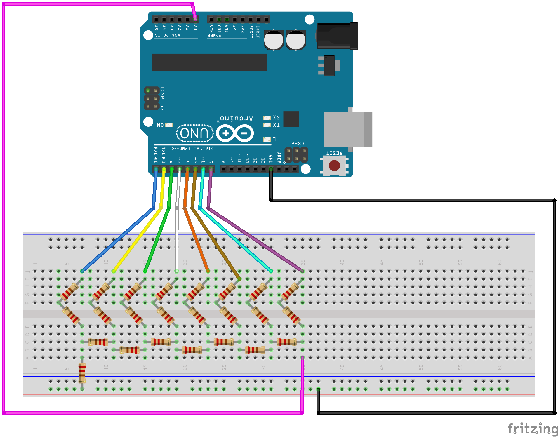
After confirming the work of the 4-bit converter, I make the 8-bit converter and aims to create a ramp wave and sine wave signal using Arduino UNO. You can see the schematic and the codes in the attachment below.
I use Arduino UNO for simplicity and because it's has 5V for its high digital output voltage. I use port D (digital pin 0-7). b0 goes to digital pin 0, b1 goes to digital pin 1, etc. Then I try to read and plot the output voltage using an oscilloscope.
Using the code for the ramp wave signal and sine wave signal, the results are like these :
But what if you don't have an oscilloscope? Don't worry, you can use analog read in the same Arduino UNO to read and plot the output voltage. It's a little bit funny though because in analog read in Arduino is using ADC to read the value. But don't worry, you can still plot the signal using serial plotter and the result is not disappointing (although it's still better to use oscilloscope). The result can be seen in the images below.
- Conclusion
In conclusion, R-2R Ladder DAC is proven to be able to convert digital signal into analog signal in simple but effective way. And for practical applications, we can use this R-2R Ladder DAC to make some cool tech like to generate audio sound with Arduino like the one explained in this project by Boris Leonov.


_ztBMuBhMHo.jpg?auto=compress%2Cformat&w=48&h=48&fit=fill&bg=ffffff)


Comments
Please log in or sign up to comment.