

Hardware components | ||||||
 |
| × | 1 | |||
| × | 1 | ||||
| × | 1 | ||||
| × | 1 | ||||
| × | 1 | ||||
 |
| × | 1 | |||
| × | 1 | ||||
| × | 1 | ||||
Software apps and online services | ||||||
 |
| |||||
Have you ever seen those cool card-swipe door systems in offices and wondered how they work? Well, you can create your own RFID-based door lock system using an Arduino, an RFID reader, and a solenoid lock. All from the comfort of your home! This project is simple, affordable, and a great way to dive into the world of smart home automation.
If you want to know detailedly, how to make RFID Door lock using Arduino, check there where I explained everything from top to bottom.
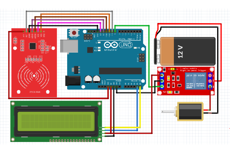
Arduino RFID Door Lock System’s Circuit Diagram:The below RFID Door Lock System circuit diagram represents how an Arduino, RFID Module, Relay module, Solenoid Lock, and LCD display are connected to create a secure and automated door lock system.
If you are a passionate hardware guy, just jump here, where I explain the working of this Arduino RFID Door Circuit Diagram in a clear way.
Still get confused with the wiring connection. For example, which pin do I want to connect to which one? No worries. check out Pinout Connection Tabulation, where I mentioned one-to-one pinout connection in an easily understandable way.
As you can see, the hardware connections are pretty easy and straightforward. The complete setup is powered by a 12V lithium battery pack, making the project portable and easy to install. For practical purposes, you can opt for a12V adapter.
We have built a lot of RFID based projects previously, if you are completely new RFID and would like to understand the basics of RFID and how it works with Arduino you can read our Arduino RFID tutorial before proceeding with this project.
Before moving on to the code that I provided, you first want to know about your Authorized RFID Tag UID value. This is essential so that our RFID Door lock can distinguish the Authorized RFID Tag from the group of unauthorized RFID Tags.
To get to know the UID details of your Authorized RFID Tag, check this RFID Tag UID Scan Code. After dumping this RFID UID Scan code, you can able to see the scanned RFID Tag UID values on the Serial monitor as well as in the Display as shown in the below images.
Just copy that UID value and replace it on the below attached code's "byte authorizedUID[] = {0x69, 0xA9, 0x81, 0x5A}; " Variable as shown in the above image.
After flashing the code and providing a proper power supply, if everything goes well, you will be able to get the result as shown here, when scanning the authorized RFID Tag.
For complete video demonstration, check this link - https://www.youtube.com/watch?v=PeGIjCImpE0
If you face any issue, while dumping the code into Arduino.Check this Arduino Troubleshooting Tutorial
.
Want to discover more cool projects? Dive into our collection of Arduino IoT Projects | Arduino Robotics Projects | Arduino AI Projects | Arduino Home Automation Projects | Raspberry Pi Projects | ESP32 Projects to inspire your next build!


Comments