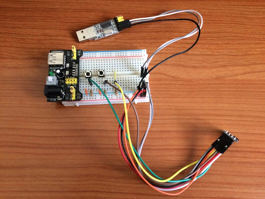
In the last months I played a lot with the NodeMCU ESP8266 Breakout Board. It is bread board friendly and it doesn't require any hardware setup.
Some days agò I got an ESP-01, it is very boring to connect and to setup so I decided to build a complete hardware evironment to emulate the NodeMCU one.
I have arranged the breadboard to have half of it available to connect other devices.
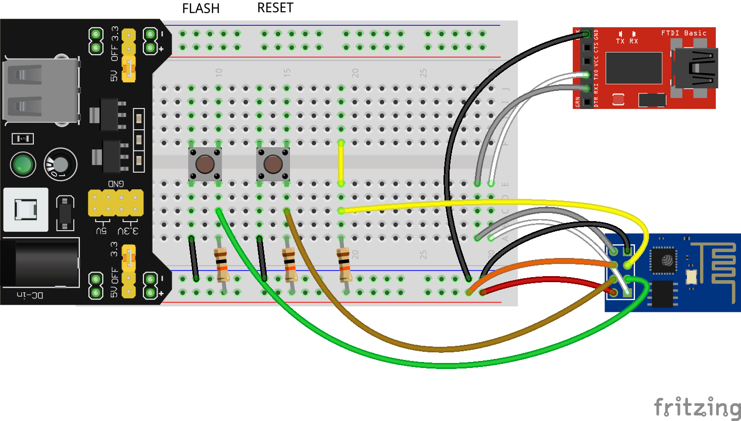
ExplanationRST, GPIO0 and GPIO2 pins are is pulled high with a 10K resistor, CH_PD is connected directly to VCC.
RST and GPIO0 can be pulled down with a switch to reset the device and/or enable the flash mode.
How To UseHard Reset: press the RESET button.
Flash mode: press the FLASH button and, without release it, press the RESET button. When flashed press the RESET button again.
GPIO0 (green wire): connected to row 10.
GPIO2 (yellow wire): connected to row 19.
Update 2017-05-28I got a couple of ESP01 Breakout:
So I rearranged the Dev Kit, same functionality, less wires.


_3u05Tpwasz.png?auto=compress%2Cformat&w=40&h=40&fit=fillmax&bg=fff&dpr=2)
Comments