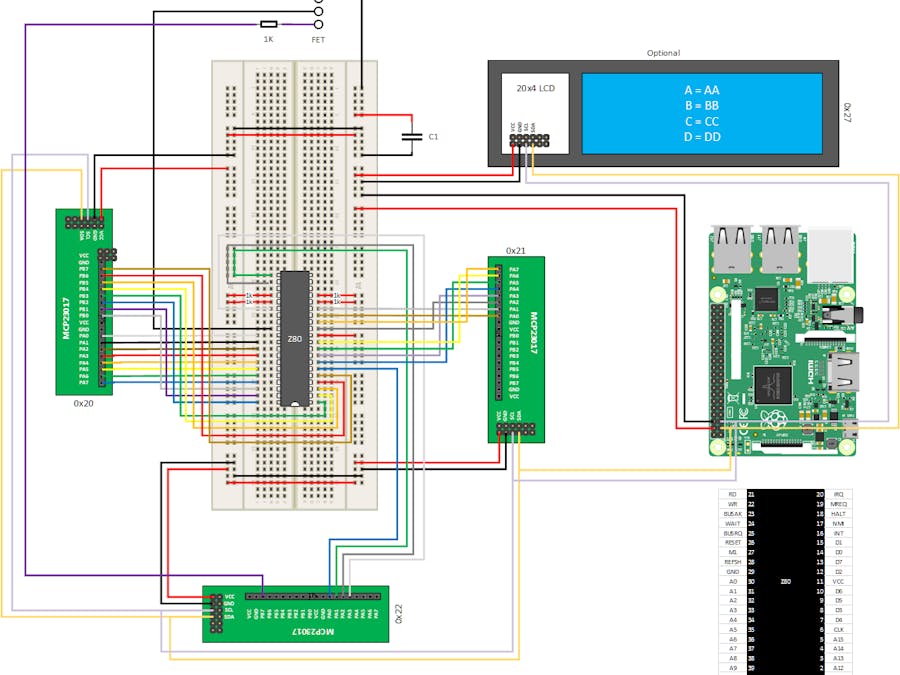
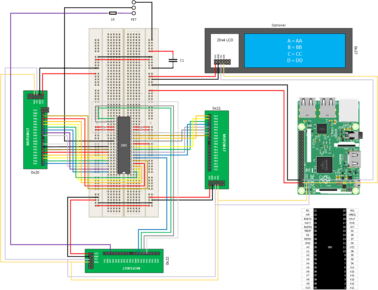
This project aims to create a Z80 to Raspberry Pi interface which will be used to map out and run use-case scenarios on the Z80 CPU. This will allow us compare real world results against subsequent emulation code. This document will describe the hardware, software and Python code required to interface directly with a Z80 CPU. An Intel 8080 compatible Z80 was chosen for its widespread adoption, excellent documentation and relatively simple 40-pin IO package. I will utilise a Raspberry Pi with multiple MCP23017 GPIO extenders to connect directly to the CPU and interact with it at the Logic level. I will also provide a Python script to send machine code to the CPU, handle RAM and external connectivity.
Aims· To be able to interact directly with the Z80 CPU at the machine code/Assembler level.
Requirements· The interface should be able to pass machine code to the CPU and receive & store the results in pseudo RAM.
· We should be able to compare the status of the CPU with subsequent emulation code. I.e. be reusable.
· Be able to pause and resume execution.
· No specialist prototyping equipment is to be used. The hobbyist should be able to re-create this project.
· We should have good visibility of the CPU, i.e. address and data bus status.
HardwareOptional LEDs can be connected to the address bus, data bus, clock, power and other outputs to aid troubleshooting. Each Led is wired in parallel with the output pin to monitor and includes an inline 330-Ohm resistor.
A small smoothing capacitor (C1) is required to reduce power fluctuations. The Raspberry Pi shares its 5v line with the USB ports, therefore the quality of the 5v line is dependent on the number and type of deceives connected to the Raspberry Pi.
The optional LCD screen can be installed to aid troubleshooting but it not required or interfaced with in the control script.
A FET is installed to cut power to the CPU when not actively running the script. This lowers power use and resets the CPU registers to default values.
Figure 1A- Wiring diagram
Figure 1B - Wiring diagram with optional LEDs
BuildMuch of the build process can be streamlined and customised to suite the builder. This section is included to demonstrate “What good looks like”, the number of connections and how much space the interface requires.
Figure 2 Shows the large 300mm enclousure and the recommended layout of slotted cable trunking. Note, this build includes 34 * 6mm holes for LEDs which will be connected to the address bus, data bus and other CPU outputs, these are not required but may aid troubleshooting.
Figure 2- Interface Enclosure
Figure 3 shows the placement of the GPIO extenders and Raspberry Pi. The Raspberry Pi and GPIO extenders are secured with small self-tapping screws.
Figure 3- Structured cabling, Raspberry Pi and GPIO extenders installed
Figure 4 shows the completed interface and the extensive amount of cabling required.
Figure 4 - Interface Complete
Interface SoftwareInstallationThe interface script has been tested with a Raspberry Pi 3 and 4 running Raspberry Pi OS XXX. The Python libraries for MCP2017 are required and are installed with the following commands
pi@raspberrypi: ~ $ Sudo python3 -m pip install --force-reinstall adafruit-blinka
pi@raspberrypi: ~ $ sudo pip3 install --upgrade --force-reinstall adafruit_circuitpython_mcp230xx
Finally copy the cpu.py Python script (attached below in the Python code section) to a suitable location on the Pi.
CodeThe main loop of the interface script provides a simulated clock cycle and pseudo RAM to the CPU, the CPU will execute machine code in the pseudo RAM as a normal CPU would in a computer.
The flow of the main loop of the interface script is detailed below in Figure 5.
Figure 5- Interface software flow
UsageTo use the interface run the Python script with or without a binary executable file specified as arguments in the command line. Without a command line option, the script will load a default built in program which displays a circle of binary 1’s in RAM, which represents a circle i.e. a Hello World.
pi@raspberrypi: ~/vasm $ Python3 cpu.py
Figure 6 - Default Output
The interface script can also run pre-compiled binary files by specifying their file name as an argument on the command line. In this example, we will execute a single test from Frank Cringles Z80 instruction exerciser.
pi@raspberrypi: ~/vasm $ Python3 cpu.py z80doc
Figure 7 - External Binary
We can also create our own binary file to execute via the creation of a Z80 assembler file. Open a file in a text editor called test.asm and enter the following assembler instructions.
org &0000 ld a,$01 ld hl,$03EB ld (hl),a My Label: Inc a Ld hl,$03EB Ld (hl),a Jr MyLabel
This code will originate the code at memory address 0000h, load the ‘a’ register with 01h, load the HL register with the address 03EBh (1000 in decimal), store the ‘a’ register in RAM at 03EBh and run through a loop incrementing and storing the ‘a’ register in RAM at 03EBh.
Compile the test.asm file with vasm using the following command:
pi@raspberrypi: ~/vasm $ vasmz80_oldstyle -Fbin -dotdir test.asm
This will create the binary file a.out which can be used as input to the interface script cpu.py with the following command:
pi@raspberrypi: ~/vasm $ Python3 cpu.py a.out
The assembled a.out file is loaded into pseudo RAM and executed by the CPU on the interface board.
Figure 8 shows two console windows comparing the assembler source code and the machine code stored in pseudo RAM. We can see how the assembler code is accurately converted to machine code and run on the actual Z80.
Figure 8- Code mapping
TroubleshootingI get a _curses.error: addstr() retruned ERR error
The python package curses can be fussy about screen sizes and struggles to show text off-screen.
Putty into your Raspberry Pi and stretch the window so its big enough to fit all text in.
I get a I2c read/write error
The MCP23017 GPIO extenders must be configured exactly as per the wiring diagram and have the correct address.
Use the i2cdetect command to ensure each of your MCP2017 GPIO extenders are addressable and have the correct address, which is shown in the wiring diagram.
Performance tuningIt is possible to speed up i2c bus considerably by editing the /boot/config file and adding
Dtparam=i2c_arm=on,i2c_arm_baudrate=1000000
Valid baud rates include 100000, 400000, 1000000, 1700000 and 3200000
The mcp23017 extenders have a maximum bandwidth of 1700000 but real world testing has shown 1000000 is the maximum achievable without the MCP23017 devices holding the i2c bus low for prolonged periods, reducing the speed improvements of a higher clocked bus.
ConclusionWith this solution we are now able to run code on a real CPU without the overhead of the OS, interrupts or shared memory all of which may or may not be documented or triggered on purpose. This greatly enhances our ability to compare the real CPU against the subsequent emulation code.
References and supporting materialVASM assembler available at http://sun.hasenbraten.de/
Frank Cringles Z80 instruction exerciser http://mdfs.net/Software/Z80/Exerciser/Spectrum/
Visio stencils used from https://github.com/rrobinet/Visio-Stencils


Comments
Please log in or sign up to comment.