Halloween really isn’t much of a thing in Peru, but it definitely is in Canada. My wife works for the Canadian embassy, and they put on a big Halloween celebration for all of the employee families posted here in Lima. It’s somehow become a big deal. Bigger than in Canada. Everyone participates.
So my son was understandably upset when there was a pumpkin carving contest the previous year, we made a basic “here you go" 5 minute pumpkin, and lost dismally.
So, somewhat stupidly… in the moment… I promised my son I’d make him a robot pumpkin and win the contest next year.
Well, here I am almost 12 months later, making a robot pumpkin.
SetupIn contrast to some of my other projects, the scope of this project is pretty straightforward.
The pumpkin has animated expressions that change depending on what it’s doing. If someone gets close to it, it randomly says a random phrase using Android's builtin text-to-speech engine. If nobody bugs it for long enough, it plays some spooky halloween sounds.
I used Android’s built in audio visualizer class to animate the facial expressions according to the sound being produced.
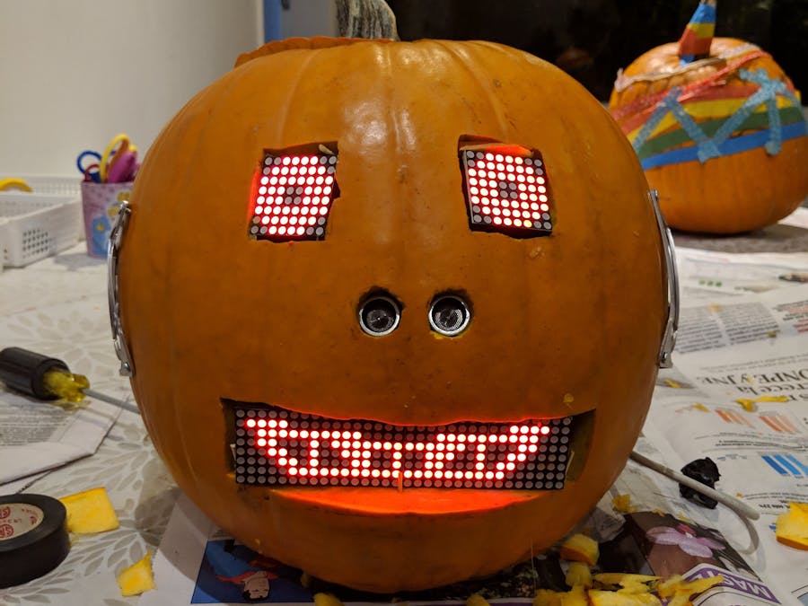
It’s basically some animated LED matrix displays for the eyes and mouth, an ultrasonic range sensor that determines when it should be chatty, and single board computer running Android Things (either a NXP Pico i.MX7D or a RPi3) with a battery and powered stereo speakers. I put the pieces together, and I got my kids to do some of the pixel art.
There’s really very little to it. Assemble the wiring as shown in the below schematics. You can find my software here (https://github.com/jpuderer/Pumpkin), which you can either flash directly onto the board, or modify to your liking first.
Instructions on compiling and flashing your board can be found here: https://developer.android.com/things/get-started/kits
There are a few caveats, so if you’re planning to reproduce this (or something like it) make sure to note:
- SPI - The SPI bus is really intended to be used as an internal bus between chips on a PCB. Using long wires to connect LED modules is not ideal, and the wires can pick up noise (and therefore glitching in the display). I've found that twisting the GND and CLK wires together helps reduce errors.
- Visualizer on the RPi3 - There is an issue with the visualizer class on the RPi3 (https://issuetracker.google.com/issues/113122591), which is not present on the NXP. I implemented fake sound data to drive the facial expressions on the RPi3, but everything works better on the NXP.
Here’s what it looked like mounted in a cardboard box (right before the pumpkin carving).
When it's show time, cut out the appropriate holes in the pumpkin for LED displays and sensors, decorate it, get pumpkin goo everywhere, and stick the electronics in. I recommend that you put the main board in some kind of enclosure and wrap the edges of any other boards in electrical tape… pumpkin goo gets into everything!
ResultsHere’s what it looks like assembled and working:
The party is the evening of the 30th (for reasons too boring to go into), so stay tuned for some results!
Update: Sadly we did not win first prize as the carving of the other pumpkins was quite impressive, but we did get a prize for originality. First prize was awarded to my friend Jose for his very cool looking pumpkin (which was much better carved). Fortunately, the prize for originality was just fine by my son.


Comments
Please log in or sign up to comment.