For more projects like this check out my website at jamespoole.me !
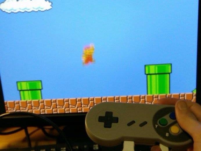
With the release of the Pi Zero, everybody has rushed to see how they can use this relatively powerful computer with such a small profile. I saw a few versions of people putting the Pi inside game controllers to host the console from within itself so I thought I would give this a go. A friend was able lend me a real SNES controller, so it became the victim of this project! Most of the similar projects online used USB controllers so I would be doing something a little different here.
My initial plan was to just cut the cable for the controller, solder the 5 wires to the pi and use the snesdev module that is a part of the Retropie operating system. For some reason that I still don’t know, I couldn’t get that to work for me so I had to figure out a different way around. I tried using a Teensy board to interface the controller to USB and plug that into the Pi, which worked, but I couldn’t manage to fit all the boards in the case.
The final, and most time consuming plan was to figure out a way to wire each individual button to the Pi which created a lot of work and headache but if I could get the software right, would almost certainly work.
Here I will explain how I went about this:
HardwareThe first step was to remove the PCB from the case and see how the buttons worked. Each button has a common ground contact and an individual Vcc contact that are connected when the button is pressed down. For this I would need to scrape away the PCB to expose the metal for each button.
Next step was to solder the wires on to the new contacts that I had exposed. This proved the most time consuming part as the PCB board was resisting the solder quite a bit but eventually all of the wires complied.
Once I had the PCB board covered, next I had to solder the other end of the wires to the unpopulated GPIO ports taking note of which button went to which port. Soldering to the unpopulated ports is not only far easier than soldering to pre-soldered pins, it is almost essential for this project as the Pi probably would fit in the case if they were present.
Now with all of the soldering done, my apparatus was ready to put into the case but a few structural adjustments were required with the Dremel. I cut openings for the cables at the bottom of the controller just big enough to fit the HDMI and the power cables.
Finally, I had to create some makeshift spacers to push the board down enough so the button presses were always registered. Once that was done, and the case was screwed together, that was the hardware element to my project complete.
SoftwareSo the first thing to download is the latest RetroPie image from the RetroPie website.
Once I had that downloaded and written onto the SD card I found the C file that would be the secret to getting this project to work. The source code is available at this Adafruit repository. Just download this folder into your home folder edit the file appropriately to match the pins that you have soldered to on the Pi. Then once you run the makefile and reboot, your buttons should be matched up. There’s plenty of instruction included on the Adafruit Github page for that part of the job.
So if that all worked, you are pretty much done. The button presses will now be recognised as keyboard strokes and you configure the controller like you would any controller. Before you screw together your case make sure to upload your ROMs to the SD card and then away you go.
Im very glad I saw this project to the end because I ended up learning a lot more than I initially expected. It took a few times to revisit over a period of time but I eventually cracked it. If you have any questions, don’t hesitate to contact me about the project.


Comments
Please log in or sign up to comment.