

Hardware components | ||||||
 |
| × | 1 | |||
 |
| × | 1 | |||
| × | 1 | ||||
 |
| × | 1 | |||
 |
| × | 1 | |||
 |
| × | 3 | |||
Software apps and online services | ||||||
 |
| |||||
Hand tools and fabrication machines | ||||||
 |
| |||||
I've wanted to build a digital clock with Arduino for a long time. There are some sold in DIY KITs around but I find the management software to be inconvenient: when you look at them they are punctually displaying the temperature or the date and you have to wait for them to display the time again!
So in the end I decided and here I am to share the project with you. I called it ASC: Another Stupid Clock :) just to laugh a bit since there are tons of digital clocks with Arduino around the net.
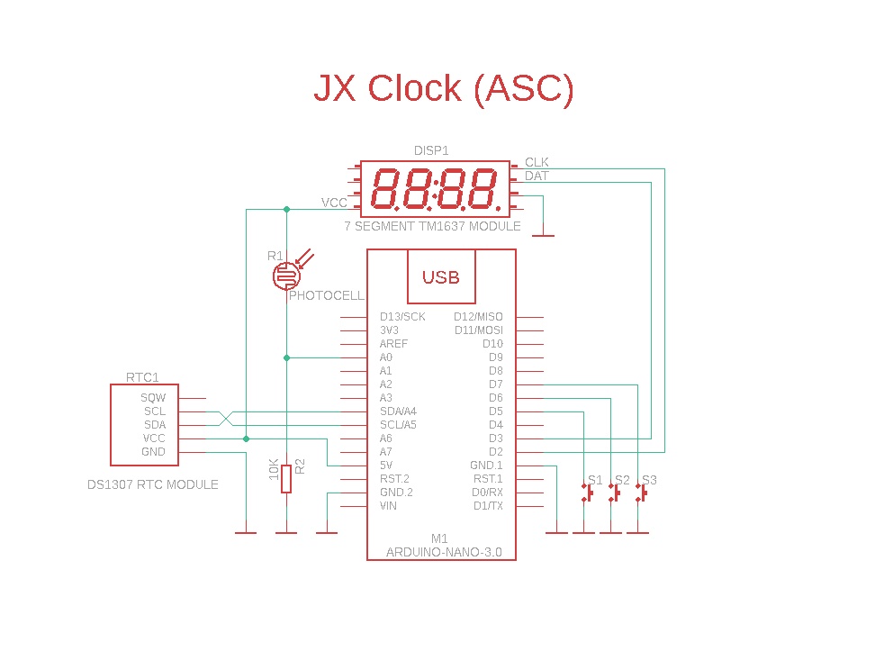
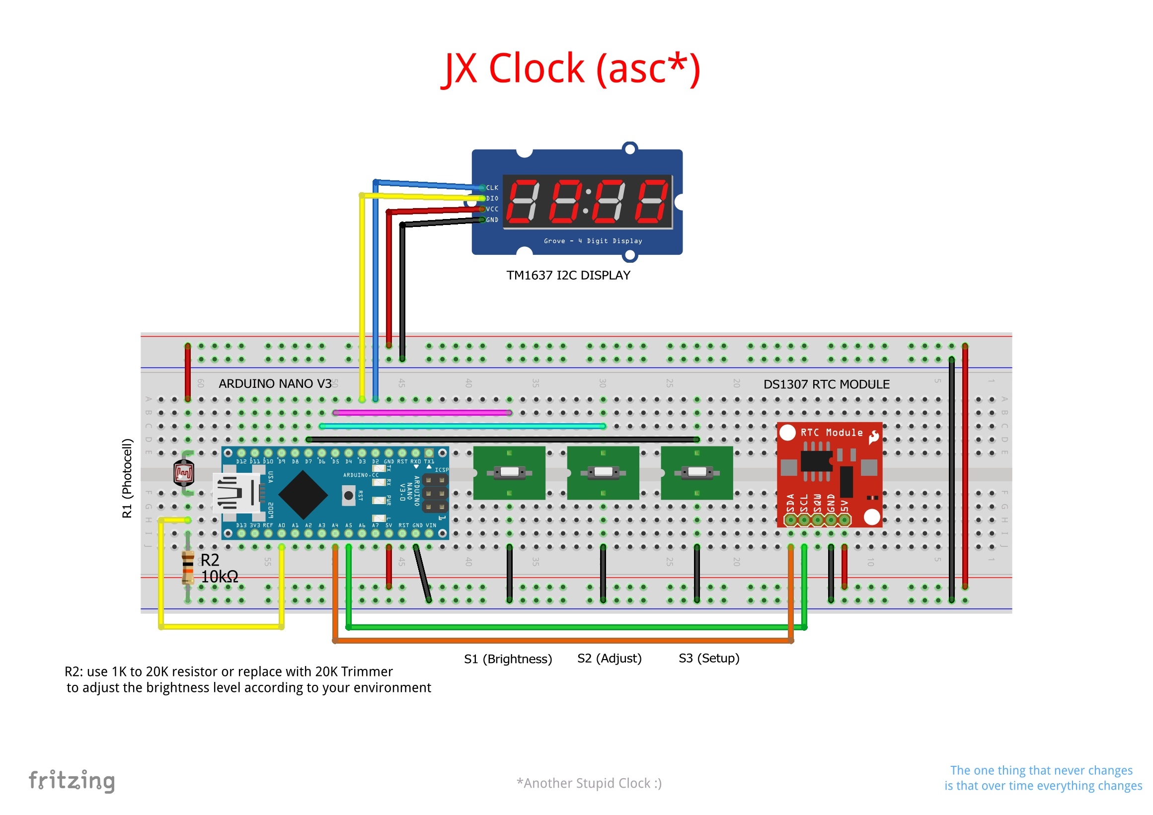
The projectis equipped with an RTC module with a buffer battery to keep the time in case of blackouts and/or moves. It allows you to adjust the date and time using the three buttons, it also allows you to set the brightness to 4 different levels or to activate the automatic brightness, useful when you keep the clock on the bedside table or in areas where at night an excessive brightness can be annoying and a too low one makes it difficult to see.
I think the project is very simple to assemble, and can be useful for beginners to learn to solder and develop code in a simple way, you can replace the RTC1307 module with a more recent one based on the DS3231SN chip, the cost is negligible, but the 1307 is fine in this context. Another thing you can do is replace the 10K resistor R2 with a higher value one to increase the light sensitivity or even better replace it with a 20K trimmer (with a 1K resistor in series) to be able to adjust the display lighting according to the ambient brightness. I used a CDS 5537 type photoresistor (18-30 KΩ at 10 Lux, 2 MΩ in the dark).
- The S1 BRI button is used to adjust the brightness. The first 4 presses change the level manually, the next press activates automatic adjustment (set as default).
- The S2 ADJ button is used to adjust the hours or minutes when in SETUP mode.
- The S3 SET button is used to enter SETUP mode and choose whether to adjust the hour or minutes or (at the third press) exit the setup mode without changing anything. If instead you press the BRIGHTNESS button after setting the time, the hours and minutes shown on the display will be saved in the RTC module.
By modifying the three #define BRI, ADJ and SET in the code you can of course use any digital pin you like.
Same thing for the analog input A0, you can use any other analog input except A4 and A5 which are the SDA / SCL pins for I2C communication with the RTC module, I have not tried but I think that even for the display you can use other digital pins other than D2 / D3.
If you leave the global variable SERIALDEBUG to True by opening the serial monitor you will be able to see the current time of the RTC module every second and also the manual brightness values or those selected by automatic brightness.
I am not interested in the alarm function so I leave it up to you to choose whether to add it. Just insert other case instructions in the switch construct and use the three buttons already present. For example, you could use the ADJ key that is not used during normal operation or add other events to the SET key, it's just a matter of imagination and inventing the right code. It can be a perfect starting point to study what I wrote.
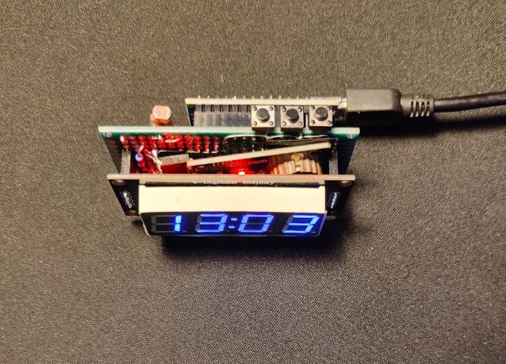
The clock can be conveniently powered with an old cell phone power supply via a USB cable directly inserted into the Arduino connector; for a small fee, you can find compatible Arduino Nanos that have the much more convenient and now more widespread USB type C connector. The absorption at maximum brightness is around 60/70 mA.
Among the photos you can "admire" the prototype that I roughly made on a multi-hole base with a couple of solderings mounting the Nano on the back and the RTC module under the display.
Have fun and... don't burn your fingers! :)
As always I apologize for the elementary translation but I used Google Translator which however has made giant steps.


_3u05Tpwasz.png?auto=compress%2Cformat&w=40&h=40&fit=fillmax&bg=fff&dpr=2)
Comments