


Hardware components | ||||||
 |
| × | 1 | |||
| × | 1 | ||||
 |
| × | 3 | |||
 |
| × | 2 | |||
 |
| × | 1 | |||
 |
| × | 1 | |||
 |
| × | 2 | |||
 |
| × | 1 | |||
 |
| × | 1 | |||
| × | 1 | ||||
Hand tools and fabrication machines | ||||||
 |
| |||||
| ||||||
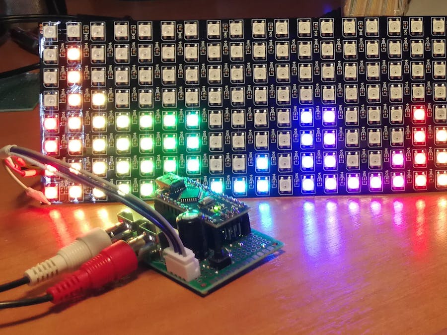
This project is for making a RGB 32-band audio (music) frequency spectrum visualizer using Arduino Nano and a 8x32 WS2812B RGB Led Matrix.
The original Project that inspired thisA great thanks goes to Shajeeb author of the original project based on the MAX72xx led matrix. I only modified the pilot part of the led matrix to adapt it to the RGB WS2812B Led Matrix.
Link to original project: 32-Band Audio Spectrum Visualizer Analyzer
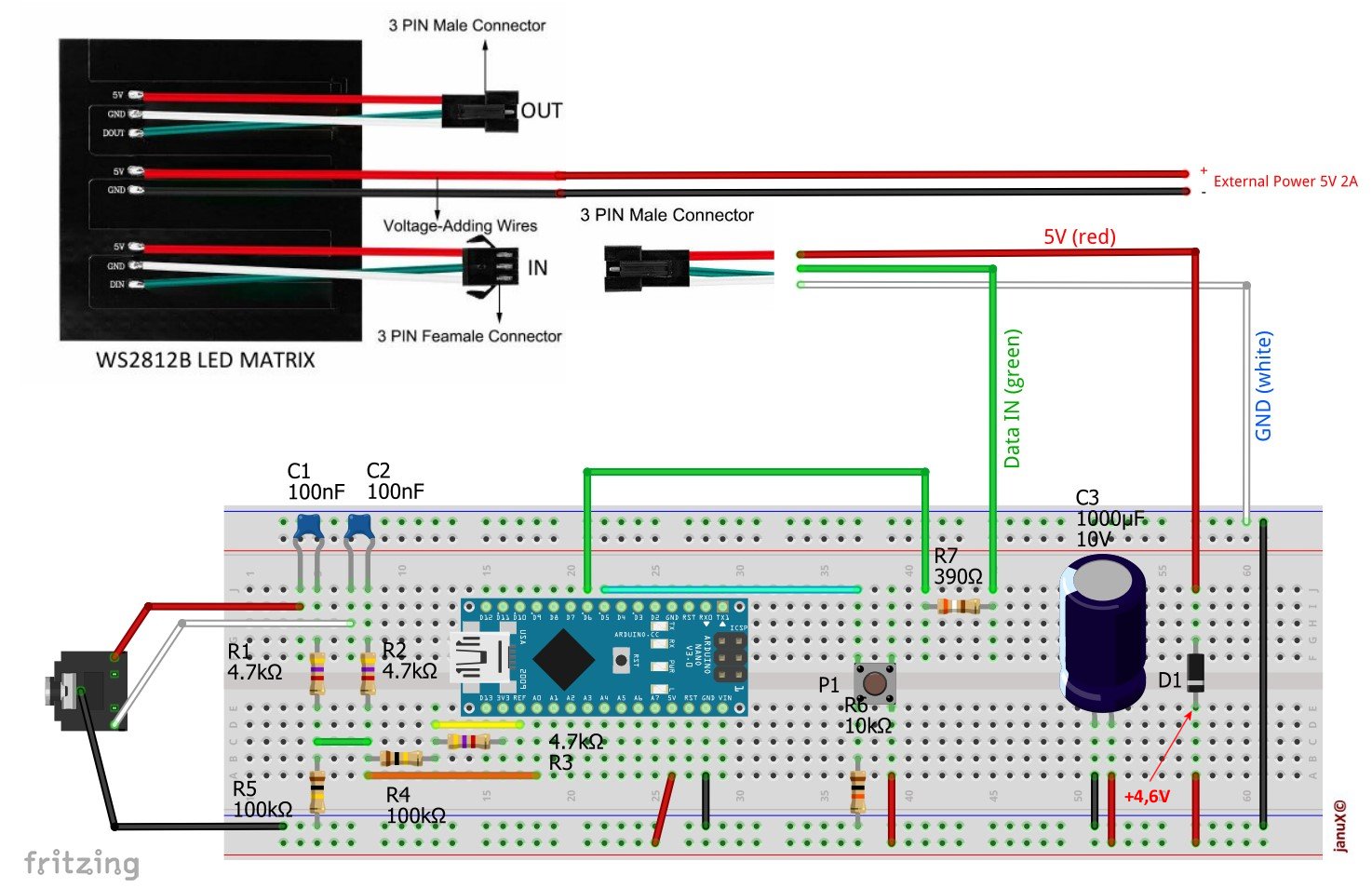
The WS2812B RGB Led MatrixUsing an RGB LED matrix based on 5050 SMD high brightness LEDs, it is necessary to use an external power supply because the RGB matrix can absorb more than 10mA per LED, therefore with all the LEDs lit at maximum brightness could absorb more than 2.5 Amperes.
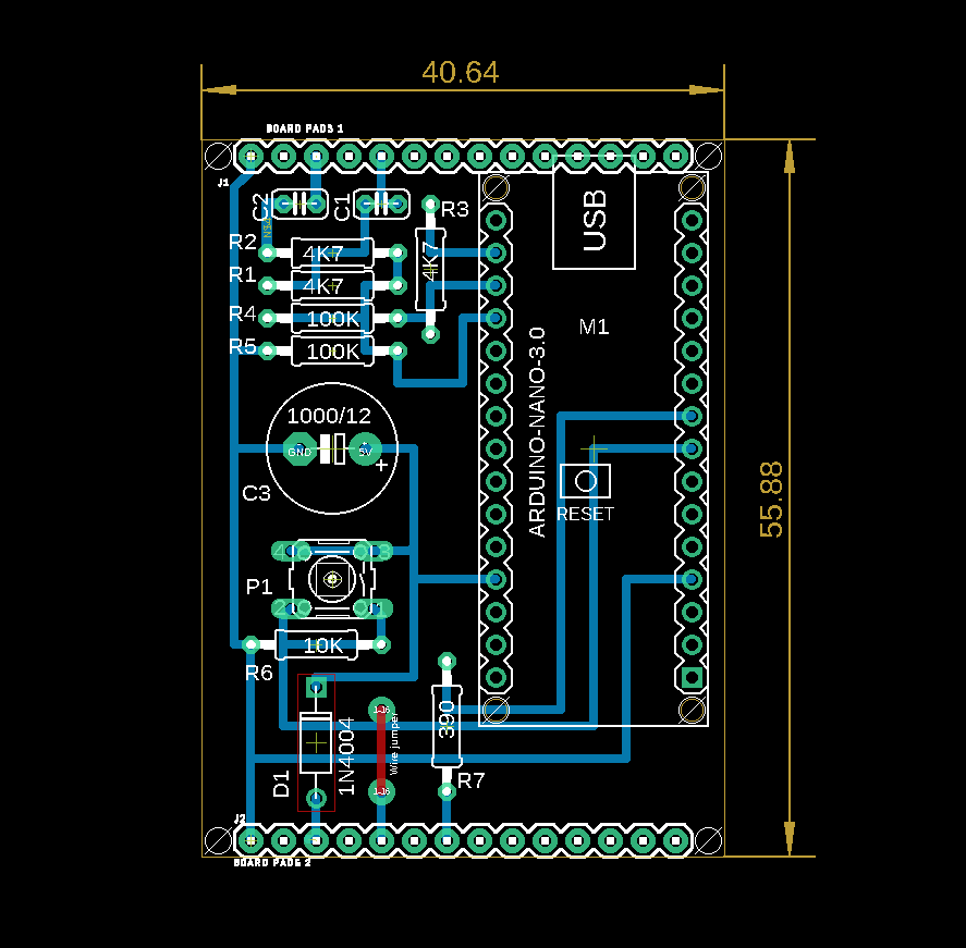
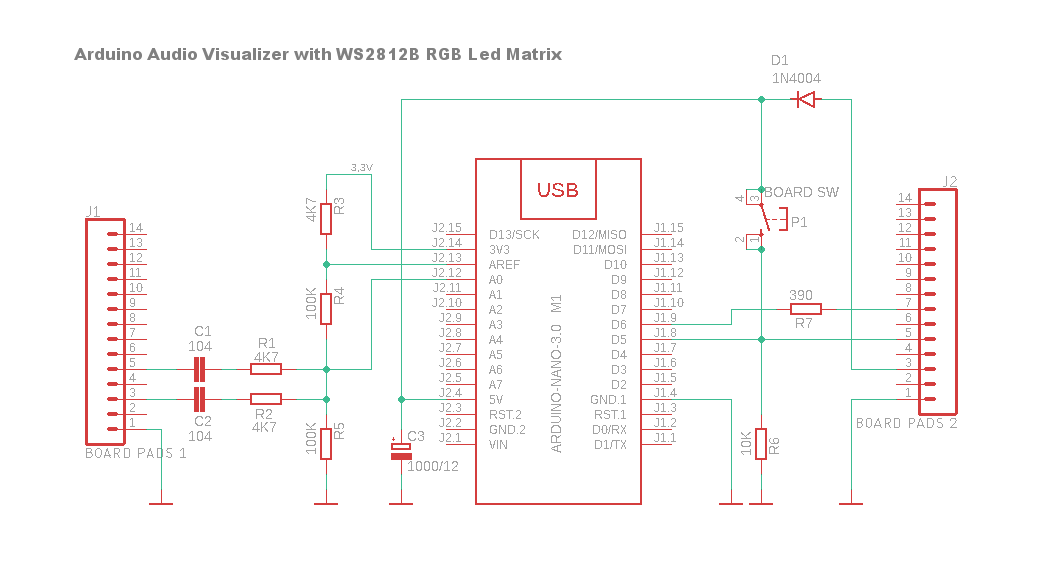
For this reason I have inserted a diode in series at +5V in order to be able to power Arduino in stand alone mode, when the USB cable is not connected, and to avoid Arduino being the power source of the RGB matrix, so you avoid overloading the internal circuits of the board with a current it could not supply.
To the original Project, in addition to the input diode, to protect the LED matrix input from possible voltage peaks, I also added a 390 ohm resistor in series between the Arduino pind D6 and the Data input, and a 1000 µF 12V capacitor to improve the Arduino supply voltage stability.
Hardware assemblyAs visible in the main photo I made the first prototype on a 4x6 cm multi-hole board using two RCA audio sockets (soldered directly on the board) which can also be replaced with a 3.5 mm female Jack socket. The important thing to avoid hum is to make the connections between the source and the card audio input with a shielded cable. Another tip is to keep the connection between the Arduino and the led matrix as short as possible.
The codeIn the end, all the software is based on the great work done by the author of the sampling procedure through the FFT library and the definitive realization of Shajeeb.
I have added two functions:
The first is GetLedFromMatrix(...) to map the matrix into rows and columns and to be able to address each of the 256 LEDs via row and column coordinates.
The second is the one - which I arbitrarily called SetColumn(...) - which turns on the LEDs of each column based on the peak value obtained by audio digitization (values between 0 and 7) and on the basis of the preset colors in a two-dimensional array. You can have fun changing the values and therefore the colors as you prefer. To simplify the code I used a sobroutine called Wheel() (taken from a demo attached to Adafruit's Neopixel library) that starting from a value between 0 and 255 returns an unsigned 32-bit long value to be passed directly to the setPixelColor function. On this you can play at will, keeping in mind the memory limitations of Arduino avoiding where possible the use of 32-bit variables to store RGB colors values.
Audio equalization
Furthermore, since I have run the tests with the audio coming from the sound card integrated in the PC motherboard, in order to improve the frequency response, I added a byte array of 32 values which in effect constitute an equalization curve to attenuate the bass and enhance the treble. If you don't need it, simply set the EQ_ON variable to false or change the attenuation level by changing the 32 values of the eq[32] array, a value of 100 leaves the amplitude unchanged, one less than 100 attenuates and one greater than 100 accentuates the frequency band.
Led brightness
The brightness of the matrix is preset in the code at 32 (BRIGHTNESS const). The maximum brightness value of the WS2812B matrix (on paper) is 255 but already with values greater than 100, the LED light unfortunately turns from white to pale yellow, it is probably necessary to supply the matrix through the two central red and black wires instead of at right side connector.
I'm still trying ...
Finally, if you use a maximum brightness of 64, a 1A power supply is probably enough, otherwise 2A is essential.
Future UdateI'm working on a new version that uses the OpenMusicLabs FHT library which turns out to be many times faster than the Arduino FFT.
Stay tuned. :)
Please forgive my bad English, I used the google translator.


_3u05Tpwasz.png?auto=compress%2Cformat&w=40&h=40&fit=fillmax&bg=fff&dpr=2)
Comments
Please log in or sign up to comment.