Introduction
In recent years there has been an increase in applications related toInternet of Things (IoT), the vast majority focused on controlling our homes,monitoring environmental data, smart cities, and so on. These new technologiesare easily applicable in different areas, being of great importance thoserelated to me dicina or IoMT (Internet of Medical things). These newapplications originate mainly from the smaller size of the devices, theintegration of different sensors and their connectivity using WiFi or Bluetooth.Thus, facilitating the measurement of different physiological and environmentalvariables such as temperature, humidity, air quality.
The IoMT allows the development of devices capable of measuring cardiacpulse, storing heart signals (ECG) or even being able to capture the signals ofour brain in order to control some object. All this, thanks to the appearanceof new smaller components, low power consumption and wireless communicationcapabilities such as Bluetooth or WiFi, among others. Thanks to its small sizeand the ability to interconnect allows us to move around our environment and atthe same time monitor our activities. Technological manufacturers haveincorporated some of these capabilities into smart clocks, which can count thenumber of steps we do per day and heart beats per minute. However, there aremany other signals that can be captured, processed and analyzed by thesedevices. For them it is necessary to extend the way of acquiring these signals,introducing new sensors to our everyday objects.
In this project we present an approximation for the introduction of IoTdevices to our clothes. These devices will be able to capture heart signals,calculate beats per minute, detect falls and possibly predict heart problems.All this with the aim of improving people's quality of life. For this, we willrely on artificial intelligence tools and automatic learning, Bluetoothcommunications, WiFi and NFC.
Description
The device used forthis project is based on the Rapid IoT development card presented by NXP. Itincorporates a wide range of sensors that can measure different variables suchas light intensity, barometric pressure, temperature, humidity, acceleration,gyroscope. It also incorporates communication protocols such as Near FieldCommunication (NFC) and Bluetooth.
This project isdivided into five parts, which are described below. The first part is theAD8232 (Figure 1), which is a differential amplifier used to acquire the heartsignal (ECG) (Figure 2).
The outputs of this module (Lo+, Lo- andoutput) are connected to the Arduino 101 mini, which takes care of signalacquisition and pre-processing. The Lo+and Lo- outputs let us know if the electrodes are making good contact with theskin. If the electrodes make bad contact these outputs return a logical 1,preventing the conversion process from analog to digital and returning a '?'.Otherwise these outputs return a logical 0, allowing the system to capture thesignal through the analog to digital converter (ADC0).
To calculate the beats per minute the arduino101 captures the heart signal for 1 minute, once acquired, the number of QRScomplexes present in the signal are counted. There is a faster way to calculatePPM. This method consists of capturing the signal for 30 seconds and the numberof QRS complexes detected in the signal is multiplied by two, this method isknown as averaged PPM. The signal acquired by the arduino 101 is stored, andthen sent to the web service.
The original idea was to send the informationacquired by the arduino to the web service, using the WebIO function present inRapid-Studio. However, this function has a bug, which does not allow POST tothe web service and according to the forums consulted this bug will be fixed inMarch. For this reason it was necessary to incorporate to the arduino 101 anNFC, which allows to transfer the stored signal (1 minute of information) tothe Rapid IoT (Figure 4).
The transmission of information through the NFCtakes place every time the user approaches the Rapi-IoT to the arduino's NFCsensor, thus the arduino writes the captured signal to the Rapid-IoT. Once theinformation has been written, it is necessary to send the information to adatabase for analysis. This database is located in the NXP cloud.
The Arduino 101 sends the heart beats perminute to the Rapid-IoT, which is fitted with an audible alarm that isactivated when the beats exceed 90 ppm and another if the beats fall below 70ppm. In this way it is possible tocontinuously monitor our daily activity.
It is remarkable the range of useful sensors thatthis system has to control our well-being. Rapid-IoT has touch sensors, whichallow us to navigate through different menus. It has accelerometer and 3Dgyroscopes (x,y,z), which are of great help because they can be used aspedometers and as fall detectors. Another sensor that incorporates is an airquality sensor, with which you can continuously monitor the air around us.There are also sensors for light intensity, humidity and temperature.
The second method of sending data from theArduino 101 to the Rapid-IoT is using an NFC system. To do this, an NFC NXPPN532 device has been added to the Arduino 101 (Figure 5).
To perform the transmission the Arduino 101stores the data in a buffer, this information is written to the Rapid-IoT NFCwhen it has been detected by the Arduino NFC. Once the information is storedinside the Rapid-IoT, it can be transmitted to our Smartphone using the samemethod (NFC). In both communication methods, the information is sent to the NXPCloud in order to be stored and displayed.
ECG DeviceConstruction
The ECG capture deviceis composed of 4 elements, three electrodes forming the einthoven triangle(Figure 6) and the AD8232 capture module.(https://en.wikipedia.org/wiki/Einthoven%27s_triangle).
The area of this triangle has beenreduced so that the device can be located above the heart, facilitating itsincorporation into clothing. Figure 7 shows the arrangement of the electrodes,made of stainless steel.
Figure 8 shows how these electrodes areconnected to the AD8232 module, which allows us to acquire the heart signal.Using the following code for the connection of the electrodes. Red=Left Arm,Black=Left Leg and Green=Right Arm.
Figure 9 shows the connection of the ECG moduleoutputs to the Arduino 101.
Figure 10 shows the connections between theArduino 101 and the NFC NXP PN532 module.
Once we have built the capture module, the nextstep is to send these signals to our Rapid IoT. To do this and as explainedbefore, we use the Bleutooth communication and/or the NFC. Within our Rapid IoTsome menus were designed, which are controlled through the tactile sensors thatthe device incorporates. Figure 11 showsthe general scheme that is embedded inside the Rapid IoT (for more informationvisit https://developer.atmosphereiot.com/documents/guides/nxpdisplayelementsguide.html).
It has 11 pages, which can be easily consultedusing the tactile sensors that the device has. The locations of these touchsensors are shown in Figure 12.
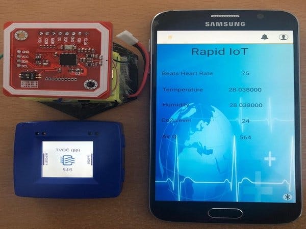
The pages allow the user to view theinformation provided by each of the sensors (Figure 13).
In order to visualize and use the informationacquired by the ECG module and the sensors located inside the Rapid IoT, anembedded application was developed inside our Smartphone (Figure 14). To accessthis application, it is necessary to install the APP NXP Rapid IoT (Figure 15).
Note: This project has been sent to 10th International Symposium on Ambient Intelligence, held in Ávila (Spain) | 26th-28th June, 2019 | www.isami-conference.net
Paper:
https://link.springer.com/chapter/10.1007/978-3-030-24097-4_16


_baVEVgguW1.jpg?auto=compress%2Cformat&w=48&h=48&fit=fill&bg=ffffff)


Comments
Please log in or sign up to comment.