Everyday when I leave for work, I never remember if I closed the garage door. So to eliminate the worry, I built this ESP8266 based garage door monitor and activator.
The ESP8266 makes this an easy way to set this up in the garage, with its low price, built-in WiFi, and a lot of GPIO. I like the Adafruit HUZZA ESP8266 (vs a bare ESP-01) with its on-board 3.3v regulator, 0.1 pin pitch, and GPIO0 button.
To activate the garage door, a relay module is used to simulate pushing the button inside the garage. This part could be omitted if you do not want to be able to open/closed the door.
This project uses a Domoticz home automation server that I have running on my Synology NAS. Any other home automation server could be used, or you could just access the ESP8266 directly over the network.
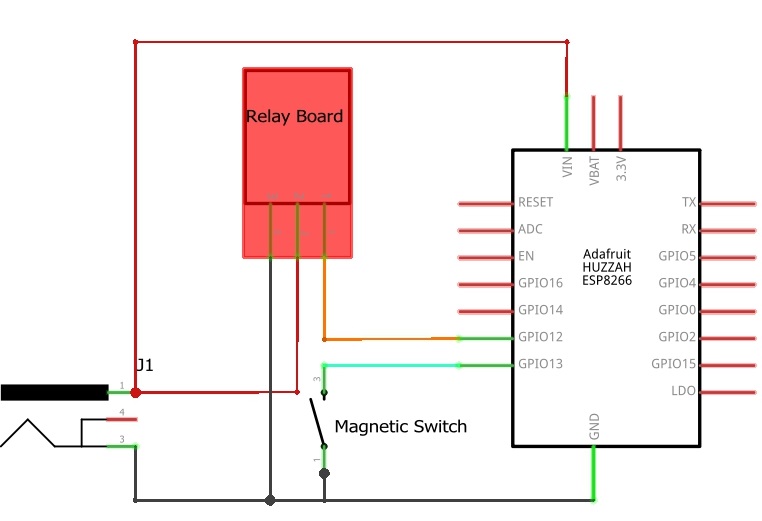
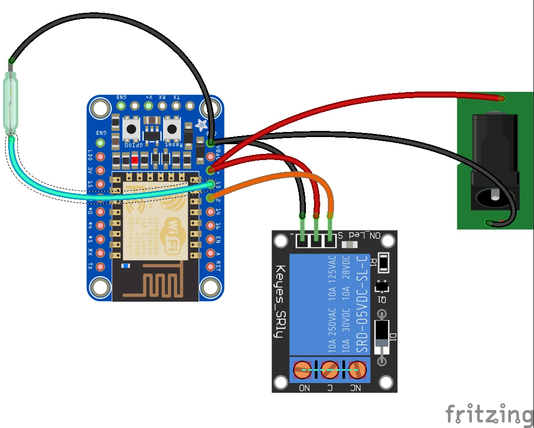
Wire everything upBelow is the circuit diagram for the whole setup. I used GPIO12 to trigger the relay, and GPIO13 to the magnetic contact switch. It is best to do this on a solder-less bread board first:
The relay module I found on Amazon has all the components already on it to control the inductive load of the relay (transistor, fly-back diode), and also a LED indicator. The relay is triggered by applying ground to the "S" pin, and 5V across the +/- pins.
The magnetic contact switch is hooked up to ground and GPIO13 is configured with a pull-up resistor. When the garage door is open, the switch is closed and GPIO13 is at 0V. When the door is closed, the magnet opens the switch, and the pull-up resistor creates 3.3V at GPIO13.
Setup DomoticzI already had a Domoticz home automation server running on my network, so I won't go into the base setup. In Domoticz the garage door is configured as a "dummy" switch, with index 12, and named "Garage Door"
After configuring the dummy switch, the button will appear under the switches tab:
Clicking on Edit, you can configure the On/Off actions. You won't know the IP address at this point. Once you create a DHCP reservation later on, then the IP address can be configured.
Domoticz has a LUA script engine that can run scripts based on certain events or times. I used this capability to send a email notification when the garage door has been open for longer than 10 minutes. It will also send a notification once the door is closed.
If you named your switch something other than "Garage Door", then you will need to edit the LUA script, since it uses the name to find the switch. Update any lines like the ones below with the new name. There are a few of them throughout the script.
otherdevices['Garage Door']
otherdevices_lastupdate['Garage Door']
Take the LUA script and place it into the scripts directory. On my server this is in /volume1/@appstore/domoticz/var/scripts/lua
The LUA script will tell Domoticz to send a notification. Then you just need to configure Domoticz to send the notification as an email (there are lots of other options too):
You'll need to change things like the Domoticz server address and port:
const IPAddress updateserver(192,168,1,100);
const int updateport = 8084;
And also the WiFi details:
const char* SSID = "YourSSID";
const char* PASS = "YourWifiPassword";
Depending on your Domoticz setup, the device index will need to be updated. In my situation it is idx=12. If you are using some other type of home automation system, then the URL would need to be setup for that API
// Make your API request:
client.print("GET /json.htm?type=command¶m=udevice&idx=12&nvalue=");
This part uses a USB-Serial converter to program the ESP8266. There is a good guide at Adafruit for programming the ESP8266 HUZZAH: https://learn.adafruit.com/adafruit-huzzah-esp8266-breakout/using-arduino-ide
Follow that guide to get the Arduino environment setup for the board. Then program the INO file that was setup in the previous step.
TestAfter successfully programming, you can test the setup before final assembly. Power up the board with a 5V supply, and connect the serial monitor in the Arduino IDE. You will see the WiFi connection status and IP address. You should be able to open a web browser and go to the IP address to view the current status.
To ensure the ESP8266 gets the same IP address every time, I configured my router with a DHCP reservation for the ESP8266's MAC address. This is necessary for configuring Domoticz to be able to open or close the door. Once the IP address is known, the Domoticz switch can be configured with this information.
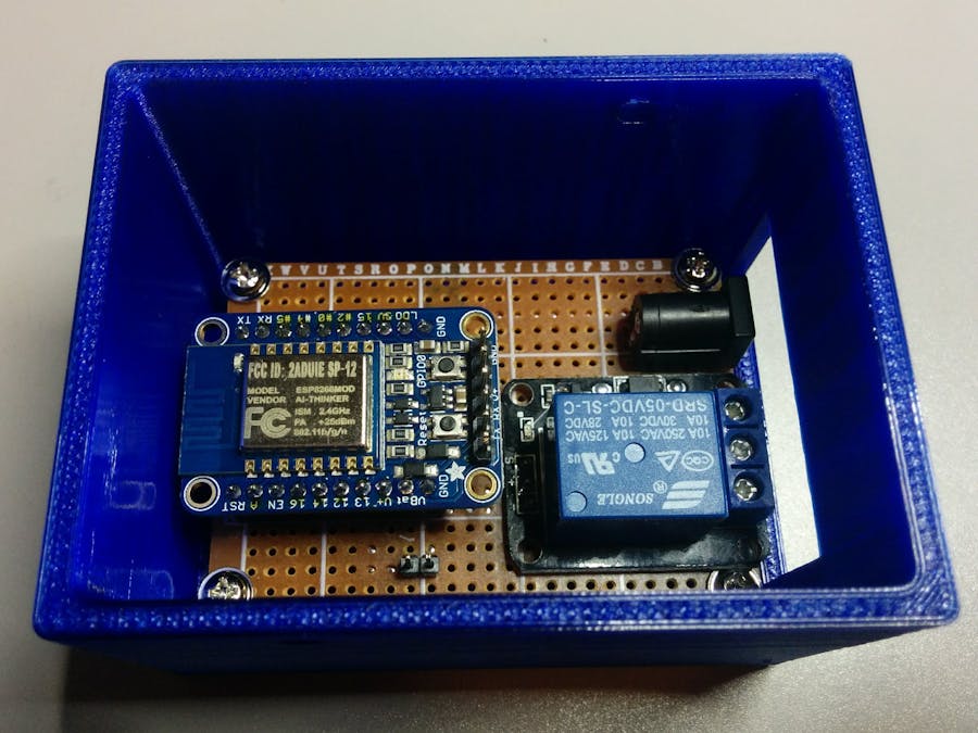
Solder everything (optional)I chose to solder everything to a perf board. But you could just leave everything on a breadboard if you want.
I designed and printed a box and lid to hold everything. STL files are included below. On the bottom of the case I put some holes for a zip-tie to pass through, so I can secure it to the garage door track.
Place the switch so that when the door is closed, the 2 pieces are almost in contact. Once the magnet is far enough away, the switch will change state.
Connect the switch to ground and GPIO13.
Run a wire to the back of the garage door opener and connect to the same terminals as the button.
Then connect one wire to the Common "C" terminal in the middle, and the other to Normally Open "NO" terminal (I used some leftover CAT5 cable that I had, and used 2 conductors for each)
Put the lid on and secure the box with a zip tie:


Comments
Please log in or sign up to comment.