See also:
Part 1. The configurator.
Part 3. Serial and IP connection (WiFi)
Part 4. The heater control
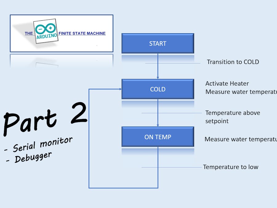
Part 2, describes the build in monitor function and the use of the VBA debugger (HMI). There are more parts to come (as long the wheater is cold and ugly) about the Arduino Finite State Machine.
When the I/O points are defined and loaded to the board, it is very nice to have some sort of tool for checking the I/O. In the standard Visual studio 2017 solution, there is a VBA debugger (HMI) and also there is a native monitor build in the sketch. First the native serial monitor (IDE); As known, it is posible to open the serial monitor inside the Arduino IDE.
When the sketch is loaded and the IDE serial monitor is started, type "h" as input. You will get the following output on the monitor:
HELP
1: Input overview
2: Output overview
3: Calc. cycle time
4: FSM State overview
5: Analoog input overview
6: Analoog output overview
7: Timer overview
8: Servo overview
9: UltraSonic overview
A: Marker overvieuw
B: Free memory, check for leaks
C: Temperature sensor overview
D: Status HMI
T: for setting the time
h: help HelpMonitor >
The most functions are self documented. The output for the different I/O types, need some explanation. e.g. help function #2, Output overview. When typing 2<return>:
Output overview at 12:46
Pin: #30 HEATER Status:0 Auto:1 Poll:0 Report:0 DB:0
Pin: #31 ALARM Status:0 Auto:1 Poll:0 Report:0 DB:0
HelpMonitor >
Another example, help function C, temperature sensor overview. When typing C<return>:
Temperature overview at 12:49
Total 1 (Onewire channel on 3)
Temp: #1 TTWATER Value:22.19 Mask: 0 Poll:0 DB:0
HelpMonitor >
In general the following applies for the data points (like DI, Temp), the status or value is presented, together with the fields Auto or Mask, Poll and DB. When the Mask/Auto bit is high, the current field value is overruled by HMI; so with the HMI it is possible to force or simulate a field value and influence the behaviour of your control. When Poll is high, the current field value will be send to HMI when changed and is send frequently to HMI (for dynamic updates the screen). The DB field will be high when you chose to write te raw field value to the MSAccess database.
Another way of presenting the currrent I/O points is by the VBA HMI tool. The tool is part of the Visual studio solution. How to connect the board to the PC will be presented in another part. It is now about the HMI and what you can expect:
The defined I/O points are presented on the HMI, when started together with some basic information from the board, like free RAM, the duration time of a cycle and the present time on the board. It is also possible to send messages to the board (see also my website for the predefined messages). When hovering over a datapoint the information about the physical pin is presented.
When using the right mouse button on a datapoint, a popup menu is presented for masking, forcing or store the information to the database. The layout of the popup menus are different per I/O type. For example the forcing of the heater:
When right clicking on the field value of the heater, it is possible to force the heater to a certain value. Normally the board is controlling the heater to switch, but is is also possible to force it to a certain value. See below:
The heater is forced on. The forcing is made visual by painting the background in yellow. The forcing is stored on the MEGA board. So; when closing HMI and starting again, the datapoint is still forced and will hold the forced value set by HMI. The same for logging to the database.
When looking at the serial monitor the output is now:
Output overview at 13:27
Pin: #30 HEATER Status:1 Auto:0 Poll:1 Report:1 DB:0
Pin: #31 ALARM Status:0 Auto:1 Poll:1 Report:1 DB:0
HelpMonitor >
Notice for datapoint HEATER status is 1 and the Auto bit is zero(0), meaning the output is forced by HMI. The Report bits are also 1 when HMI is running. This is automatically done when HMI is started; the known datapoints are send from the board to HMI by the predefined Get Metadata Information message (@GMI).
The next part of the Arduino Finite State machine is about the serial and Wifi connection between the board and your PC.See also www.jbsiemonsma.nl


_wzec989qrF.jpg?auto=compress%2Cformat&w=48&h=48&fit=fill&bg=ffffff)


Comments