


Hardware components | ||||||
 |
| × | 1 | |||
| × | 1 | ||||
 |
| × | 1 | |||
 |
| × | 1 | |||
 |
| × | 1 | |||
 |
| × | 1 | |||
 |
| × | 1 | |||
| × | 1 | ||||
| × | 1 | ||||
 |
| × | 1 | |||
 |
| × | 1 | |||
 |
| × | 1 | |||
Software apps and online services | ||||||
 |
| |||||
 |
| |||||
Hand tools and fabrication machines | ||||||
 |
| |||||
 |
| |||||
 |
| |||||
| ||||||
 |
| |||||
Note: If you don't want to go through the hassle of building this yourself, you can buy the completed circuit from me on Tindie.
IntroI live in a gated complex, so every time a friend comes to visit I have to remotely open the gate for them. Unfortunately my wireless gate opener remote only works from one distant corner of my house in front of a certain window.
I'm lazy, so I decided to hack a gate opener remote and connect it to a Raspberry Pi so that I can just leave the Pi/gate opener in that room.
Now when a friend wants to get in I just open up a web page on my smartphone and open the gate using that! I used a Raspberry Pi Zero W, but you could also use a different Raspberry Pi or an Arduino or ESP8266 just as easily—you'd only have to make some minor modifications.
This tutorial uses a 300 MHz key-chain remote gate opener, but you could also use a different gate opener remote with minor modifications—the principle will be the same.
Let's get started!
0. PrerequisitesThis tutorial assumes you have a basic understanding of electronics (what a diode/transistor/resistor/relay is, and some basic soldering skills).
1. Hacking the Gate OpenerThe first step is to open up the gate opener remote. The model I used has a screw on the back and a notch on the side. Remove the screw, insert a coin into the notch, and then twist to pop open the plastic shell.
While you've got it open, set the 10 DIP switches to match the code for your gate opener.
Next we need to identify four points:
- The positive battery terminal,
- The negative battery terminal,
- The two terminals for the button that activates the remote.
We need to remove these parts because we're going to solder our own parts in their place. Using a soldering iron you can heat up the solder connections for each part and then use a pair of pliers to gently pull them out. A helping-hands tool helps a lot here, as does patience. You can also try using some solder-wick to remove some solder.
If you get stuck, try searching for tutorials on how to de-solder components.
Once the parts are removed, use the solder pump to clean up the remaining solder from the through holes. When you're done, it should look like this:
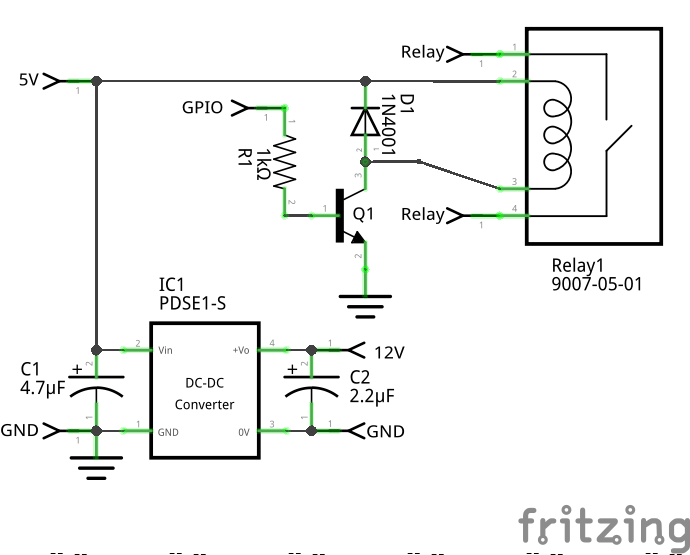
The controller circuit serves two purposes:
- It supplies power to the gate opener remote (since we removed the battery terminals), and
- It triggers the gate opener remote by using a relay in place of the button we removed in Step 1.
The battery for this particular remote was 12V, so we supply power using a 5V to 12V DC-DC converter. Per the converter's datasheet, we add a couple capacitors to either side to stabilize things.
Note: If your remote uses a different voltage battery, you should substitute in a DC-DC converter that will supply the appropriate voltage. Also, if you want to use the circuit with an Arduino or ESP8266, you might have to switch to a DC-DC converter that has a 3.3V input depending on the model (instead of the 5V the Raspberry Pi provides).
Since a Raspberry Pi can't drive a relay directly (it requires more current than the Raspberry Pi's GPIO pins can provide) we instead hook the Raspberry Pi up to a transistor, which in turn drives the relay. To make it all work we also add a resistor in line between the Raspberry Pi's GPIO pin and the transistor, and a diode parallel with the relay to make sure current only flows the way we want it to.
Note: If you want to use the circuit with an Arduino or ESP8266 that only has 3.3V power handy, you should switch to a 3.3V relay instead of the 5V relay listed.
3. Assembling the Controller CircuitFor actually building the controller circuit you have three options:
- Use perf board and connect the components together as shown in the schematic above,
- Grab a copy of the PCB I designed and send it off to your favorite PCB fabrication service, or
- Buy the PCB directly from me on Tindie (I have a few spares).
Assembling the controller circuit should only require basic soldering skills since I designed the PCB without any surface-mount parts. Just insert the components in the right spot, flip the board over, solder, and clip the remaining leads.
If you're using my PCB I recommend starting with the components in the center and working your way outward.
If you're using perf board you can still use the PCB to guide you on how to lay out your circuit—it was designed so the traces are pretty short and almost all the leads that need to be connected are pretty close to each other.
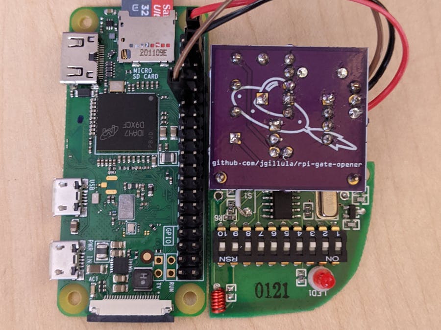
Once you're done wiring up the components (sans connectors) it should look something like this.
Now we'll wire up the connectors to the gate opener remote board.
The PCB was designed so that if you solder up a single male header pin to the through holes marked 12V and GND at either corner of the PCB, it will line up precisely with the through holes on the gate opener remote board. Solder those header pins on to the controller circuit PCB, but don't connect the gate opener remote board yet.
Alternatively if you're using perf board or a different gate opener remote, you can just solder some hookup wire to the 12V power and ground from the controller circuit's power supply. We'll connect it to the gate opener remote board shortly.
Next cut 4-5cm of hookup wire and strip 3-4mm off either end. Solder one end to one of the through holes marked "Relay", and leave the other hanging in the air. Repeat the process with a second length of hookup wire and the other through hole marked "Relay."
Now take one end of the relay hookup wire hanging in the air and solder it to one of the button through holes on the gate opener remote board we identified way back in step one. Repeat the process for the other relay hookup wire and the other button through hole.
Finally align the gate opener remote board with the controller circuit PCB so that the 12V pin slides through the positive battery terminal through hole, and the ground pin slides through the negative battery terminal through hole. Solder both connections to make them stay, and we're done connecting the gate opener remote board!
Again, if you're using perf board or a different gate opener remote, just connect hookup wire from the output of the controller circuit power supply to where the positive battery terminal was on the gate opener, and similarly for ground and the negative battery terminal.
5. Connecting the Controller Circuit to the Raspberry PiLast but not least we need to wire up the controller circuit to the Raspberry Pi. The easiest way to do this is to take three female-female jumper wires (one red, one black, and one any other color) and snip them in half as shown in Figure 9. Strip 3-4mm off the cut end of each wire, and then solder:
- The red wire to the through hole marked 5V on the controller circuit PCB,
- The black wire to the through hole marked GND,
- The other wire to the through hole marked GPIO.
Now all you have to do is plug the female socket from each wire into the appropriate header pin on your Raspberry Pi! I used pin 2 for 5V power, 6 for ground, and 11 (GPIO 17) for GPIO, but you can use whatever pins are available.
Now that we've done all the hard work controlling the gate is easy. Just make sure you have RPi.GPIO installed on your Raspberry Pi, and you can open the gate by briefly toggling the GPIO pin you connected to high. Here's some example Python code:
from RPi.GPIO import GPIO
import time

GPIO.setmode(GPIO.BOARD)
# I used GPIO 17, which is pin 11 on the Raspberry Pi header per https://pinout.xyz/
GPIO.setup(11, GPIO.OUT)
GPIO.output(11, GPIO.HIGH) # Simulate pressing the button on the gate opener remote...
time.sleep(0.25) # Leaving it pressed for a quarter of a second...
GPIO.output(11, GPIO.LOW) # And then releasing it
If you use Home Assistant then keep reading to see how to configure the gate opener to talk to Home Assistant over MQTT. Otherwise, you can use any software you like—all you have to do is make sure it eventually toggles the GPIO pin whenever you want to open the gate.
7. Bonus: Controlling the Gate via MQTT and Home Assistant!Note: This section assumes you already have Home Assistant and an MQTT server running somewhere. (It can be the same Raspberry Pi you're using to control the gate opener, but it doesn't have to be. As long as the gate opener Raspberry Pi can talk to the MQTT server, you should be fine.) If you need to figure out how to set up Home Assistant and an MQTT server, there are many other tutorials out there which will walk you through the process.
At a high level, we need three components in order to control the gate via MQTT and Home Assistant (besides Home Assistant and the MQTT server, of course):
- A Python script that connects to the MQTT server, listens for "open" messages, and uses RPi.GPIO to toggle the gate opener remote when it receives those messages.
- A systemd service that will automatically start the Python script when the Raspberry Pi boots.
- A Home Assistant script that sends the "open" message to the Python script via MQTT when triggered.
Luckily for you I've already written all three components and packaged them together in my Github repository!
To get started clone the Github repo by doing the following on the Raspberry Pi that is connected to the gate opener remote:
git clone https://github.com/jgillula/rpi-gate-opener.git
cd rpi-gate-opener
The Python script that connects to the MQTT server and controls the gate opener remote is in src/mqtt-gate-opener.py. It's already setup, so we don't really need to touch it (but you're welcome to look at it if you want to understand how it works).
Now that we have the script, we need to install it and set up the systemd service to run it when the Raspberry Pi boots.
To do that we'll first configure our installation using the configure script in the git repo. The configure script takes several options. If you don't understand these options, you can just run the script as below and it will use sane defaults for you.
--with-virtualenv— The gate opener remote code uses the RPi.GPIO and paho.mqtt Python packages. If you've already installed those globally then you can omit the--with-virtualenvand the gate opener remote code will run in the global Python environment. Otherwise, leave it in and the installation script will create a virtual environment, install RPi.GPIO and paho.mqtt into it, and make sure the Python script runs in it.--prefix=PREFIX— By default the installation script will install files into/usr/local/etc/and/usr/local/lib/. If you want to install the gate opener remote code somewhere besides/usr/local/, you can specify a different directory prefix with this option.SERVICE_USER=user— The gate opener remote service will run as the user 'pi' if that user exists, or root if it doesn't. If you want to run as a different user, you can specify which user by setting theSERVICE_USERenvironment variable to the user you want.
Again, if you have no idea what these options are referring to, you can just ignore them and do:
./configure --with-virtualenvand you'll get sane defaults that should work on any system.
Next, install the gate opener remote code on the Raspberry Pi by doing:
make
sudo make install
Finally we need to configure the gate opener remote code to use the right MQTT server and GPIO pin. To do so, edit /usr/local/etc/mqtt-gate-opener.conf. (If you changed the installation prefix via the configure script, then your mqtt-gate-opener.conf file will be in PREFIX/etc/mqtt-gate-opener.conf.) It will look like:
[Gate Opener]
GPIO_PIN = 11
mqtt_server = localhost
mqtt_server_port = 1883
Here's what each of those variables mean:
GPIO_PIN— Whichever pin you connected the gate opener controller circuit to (using the board pin number)mqtt_server— The hostname or IP address of your MQTT server. If the MQTT server is running on the same Raspberry Pi that's connected to the gate opener remote, you can leave this aslocalhost. If your MQTT server is running on your Home Assistant machine, this should be the hostname or IP address of your Home Assistant machine.mqtt_server_port— If you're using a non-default port for the MQTT server, you can change it here.
Edit these values to fit your setup and then restart the mqtt-gate-opener service by calling
sudo systemctl restart mqtt-gate-opener.serviceYou can then verify that the service is running by doing
systemctl status mqtt-gate-opener.serviceIf the service is running properly, you should see Active: active (running) on the third line. (If you see Active: failed, double check that your entered mqtt_server and mqtt_server_port correctly in mqtt-gate-opener.conf, and try restarting the service.)
Now that we've got the Python script running on the Raspberry Pi, the last step is to set up the Home Assistant script that will send MQTT messages to that Python script.
There's a simple example of such a Home Assistant script in the git repo in src/home_assistant_script.yaml. It looks like:
open_gate
  alias: Open the gate
  sequence:
  - service: mqtt.publish
    data:
      topic: "gate-opener/open"
      payload: "home-assistant"
This simple Home Assistant script does one thing: it publishes a message on the "gate-opener/open" topic with the payload "home-assistant" over MQTT.
To add this script to Home Assistant, you need to copy and paste the lines above into your scripts.yaml file on whatever machine is running Home Assistant. If you need help finding your scripts.yaml file, refer to the Home Assistant documentation.
Once you've added those lines to scripts.yaml, restart Home Assistant to make sure it detects the new script. Depending on how you've configured the Home Assistant UI, you may also need to explicitly add a card for it on your Home Assistant dashboard.
And that's it! To open your gate, just execute the "Open the gate" script from Home Assistant and watch the magic happen!
8. Double Bonus: Controlling the Gate Without Home Assistant!Note: This section assumes you already have an MQTT broker running somewhere. (It can be the same Raspberry Pi you're using to control the gate opener, but it doesn't have to be. As long as the gate opener Raspberry Pi can talk to the MQTT server, you should be fine.)
It also assumes that you can access that MQTT broker from the Internet. If you need help setting that up, you can check out my tutorial here on how to setup mosquitto with a dynamic DNS domain name from DuckDNS, username/password authentication, access controls, and TLS using a certificate from Let's Encrypt.
To access the gate opener from anywhere, you can use a docker image I put together, available on Docker Hub at https://hub.docker.com/r/flyingsaucrdude/mqtt-gate-opener-remote. That docker container uses a Python script running Flask and paho-mqtt to host a website that allows you to trigger the gate opener via the web.
Just host the docker image on your favorite service. Google Cloud Run offers a free tier which should more than cover running this simple docker container. For instructions on how to do so, see here.
To configure the docker container, set the following environment variables:
PORT— (Required) The port your docker container should listen on for web trafficMQTT_SERVER_HOSTNAME— (Required) The hostname of your MQTT brokerMQTT_SERVER_PORT— (Optional) The port of your MQTT broker. Defaults to8883.MQTT_SERVER_USERNAME— (Optional) The username to use to log in to the MQTT broker. If not given, the MQTT client won't use a username/password.MQTT_SERVER_PASSWORD— (Optional) The password to use to log in to the MQTT broker. If not given, the MQTT client won't use a username/password.MQTT_USE_TLS— (Optional) Whether or not to use an encrypted TLS connection to connect to the MQTT broker, including verifying that it has a valid certificate. Defaults totrue. Set tofalseto disable encryption.MQTT_COMMAND_TOPIC— (Optional) The topic to use to trigger the gate opener. Defaults togate-opener/open.MQTT_RESPONSE_TOPIC— (Optional) The topic to listen on to receive confirmation messages from the gate opener. Defaults togate-opener/opened.ACCESS_TOKENS_LIST— (Required) A json list of access tokens to use to access the service on the web. These tokens are the only thing protecting your gate opener from being accessed by anyone, so they should be long and random so that they can't be guessed or brute-forced, e.g.['token1-I2JJVsEV5LCfbDqMMM1iL5rCh3VaNiqKNN2RQZrkZv7BjV7MShEmwxFXsx1210J6', 'token2-H3udRjyhuXKOUi2OU8E6PGpST5S78Fc79lDeftVurht6QKIbyqxZHsftIp8NMvfE']
Once you have your container running, you can access it over the web by visiting
https://hostname.of.your.docker.container/ACCESS_TOKEN/where ACCESS_TOKEN is one of the access tokens from the ACCESS_TOKENS_LIST.
As you can see, instead of requiring a username or password, the website's security depends on the uniqueness and length of the access tokens you choose. The downside is that you must use very long (I recommend greater than 64 characters) and random (i.e. generated by your computer) tokens. You can generate such a token with the simple Python script:
import secrets, string
''.join(secrets.choice(string.ascii_uppercase + string.ascii_lowercase + string.digits) for _ in range(64))
Although the resulting access URLs aren't memorable, they are persistent, bookmarkable, and shareable, so you can, e.g., give a unique access token/URL to each of your friends and family, and all they have to do is bookmark that URL to be able to come back and open your gate whenever they need to.
9. Issues, Questions, and CommentsIf you have any issues or questions about the above instructions, please drop me a line in the comment section below. I'd love to help!
And if you have any problem with the code, feel free to open an issue on Github.
Thanks for reading, and I hope you've found this tutorial useful!


Comments
Please log in or sign up to comment.