

Hardware components | ||||||
 |
| × | 1 | |||
Software apps and online services | ||||||
| ||||||
 |
| |||||
To debug using the Axi4_lite interface, we first utilize ILA (Integrated Logic Analyzer). ILA is a feature that allows monitoring of several signals when hardware malfunctions occur on an FPGA. ILA is provided by Xilinx as an IP.
"I followed the lecture content of 'Design Self-study Matbee'."
FlowFirst, create an AXI4 Peripheral using Xilinx tools.
Set DATA Width to 32 bits and Number of Registers to 4.
Select "Verify Peripheral IP using AXI4 VIP" to enable simulation alongside the template code. Click Finish. ( VIP : Verification IP) This will automatically open the waveform.
Add S00-AXI to verify the simulation results. Confirm Write and Read operations.
Verify that the addresses for the four registers (#1, #2, #3, #4) are allocated at 0, 4, 8, and C respectively, with data values 1, 2, 3, and 4 written to each register.
In the Read section, confirm reading from registers #1, #2, #3, and #4 with addresses 0, 4, 8, and C respectively, retrieving the values 1, 2, 3, and 4 as written during the Write operations.
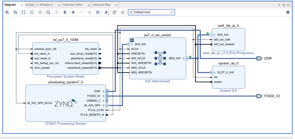
AXI4_lite IP and VIP are connected via in and out ports.
Open a new project and load the created AXI4_lite IP and Zynq.
Set the Zynq clock to 100MHz.
Press Debug and then Run Connection Automation to automatically connect the ILA.
The ILA has been added. It can trigger signals from AXI4_lite IP and capture them as dump files in the waveform.
Use the Address Editor to view the address of slave.axi from Zynq. There are four register maps, each 4 bytes, totaling 16 bytes for the AXI4_lite IP operation. The Range is 64K bits, ensuring sufficient address size.
Confirm the AXI4_lite IP's mapping to the actual PS in 64K bits, allocated from 0x43c0_0000 to 0x43c1_0000. This illustrates the control of numerous IPs through interfaces.
In Vitis, confirm writing and reading values to and from registers through AXI4_lite on the board.
Return to Vivado and use Open Hardware Manager to verify ILA's operation with Open Target - Auto Connection.
Use ILA modules to capture signals on the AXI4 Lite interface and verify them on the waveform. When AW_READY and AW_VALID signals are both 1, it indicates triggering to receive dump files. This marks the point of triggering for AWVALID and AWREADY.
Perform four Write operations, initiating a handshake at Address 0 and writing DATA 1.
When RREADY and RVALID signals perform a handshake, the READ operation occurs.
Four reading operations were performed on each address, and the data values (1, 2, 3, 4) written earlier were correctly read.
I'm currently verifying the operation of AXI4_lite in Vitis.
RX Signal
"Rx" stands for "Receive, " and "Tx" stands for "Transmit." Through the blinking of the light, we can confirm that the FPGA board is receiving signals from the Zynq.
SUMMARYUnderstanding the operation of AXI4 Interface through ILA is essential for controlling the memory of numerous IPs in various projects, which was learned through this projects.


Comments