Drawing Machine : Art Using Flour and Magnets
Original Design Concept: My original concept for the drawing machine was utilizing two different stepper motors to create interesting designs and pattern in sand.
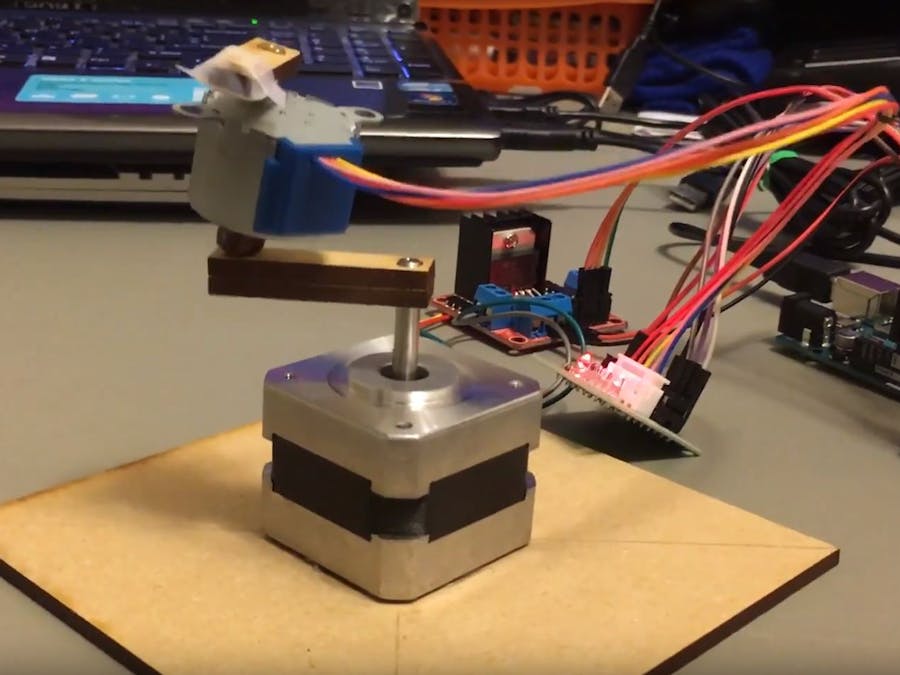
Mechanism: One stepper motor would be stationary while the other stepper motor would be placed on a lever connected to the original stepper motor and spin in a circle while drawing its own circle.
On top of the final level would be a magnet and above this entire assembly would be an iron/steel ball filled with sand. As the servo motors moved, the magnet would drag the ball across the sand and form patterns.
Believe it or not, almost 1/3rd of the time I spent on this project was used to create the above 2 levers. The reason for this is because the unique holes had to be toleranced so that they fit just snug onto the stepper motor pins. This meant multiple iterations on the laser cutter to get just the perfect fit.
Troubleshooting: This was the point in the project at which I was having the most difficulty. With the current design, I just could not get the steel ball to consistently draw in the quinoa. It was a delicate balancing act: too little distance between the magnet and the steel ball would cause the low torque base stepper motor to stall. However too much distance would cause the stepper motor with the magnet to run off leaving the steel ball behind. In the end, my original design was just not robust enough. I therefore had to downsize my project and just include the base stepper motor
Drawing Machine Reflection:
In the end, I was able to create a drawing machine that utilized the original mechanism that I had envisioned. (See above video). Although the dual stepper motor idea was simply not robust enough, I am still very I am very proud of my work. This project gave me much more laser cutting experience, especially with respect to strict dimensions tolerancing. in addition, the project allowed me to explore stepper motors in much greater detail along with the Arduino code that accompanies them.
-------------------------------------------------------------------------------------------------------------
Do it Yourself Arduino Shield
Strip-Board Alignment: I first laid the soldering board on top of the Arduino to line up the pins with the holes . Afterwards, I soldered one connection on each of the 3 Arduino blocks to lock them into place. Finally, I took the locked pins and board assembly off the Arduino and soldered them away from the micro-controller to prevent any potential damage caused by the heat conducting through the pins
Circuit Assembly: I first soldered on all the components (resistors, LEDs and Servo Header Pins), Afterwards, I ran a ground and power bus along all the LEDs and Resistors respectively in addition to the Servo Header pins. Finally, I connected each bus to their respective pins that eventually feed into the Arduino
DIY Arduino Shield Reflection:
This project was great practice as it gave me a lot more soldering experience. One problem I did run into during the course of this homework was that sometimes the soldering iron's tip would not heat up for some reason. While in the Invention Lab, I actually switched out 2 different soldering irons before I finally managed to obtain one that worked as intended. However, other than that little hiccup, the Arduino Shield project was relatively straight forward.


_ztBMuBhMHo.jpg?auto=compress%2Cformat&w=48&h=48&fit=fill&bg=ffffff)

Comments
Please log in or sign up to comment.