

Hardware components | ||||||
| × | 1 | ||||
_ztBMuBhMHo.jpg?auto=compress%2Cformat&w=48&h=48&fit=fill&bg=ffffff) |
| × | 1 | |||
| × | 1 | ||||
| × | 6 | ||||
Software apps and online services | ||||||
 |
| |||||
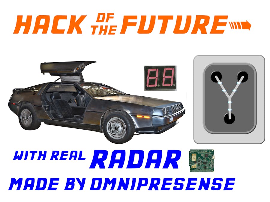
I’m a fan of the Back to the Future movies, and have always wanted my own Flux Capacitor. I also want a DeLorean with functioning time travelling circuit, but that's still out of reach. I can, however, share an Arduino sketch that engages when going 88! I can do that with a RADAR shield from OmniPreSense, and if you read on, you can too. OmniPreSense (I’m a co-founder) recently released upgraded hardware and firmware which has Serial/UART capabilities, opening it to the realm of Arduino.
Come with me as we take a journey through time, ending with a futuristic DIY flux capacitor! First, we'll just use the OmniPresense OPS241 as a shield, then make it better by wiring the RADAR to the hardware IO pins. Next, we'll add a 1980's-style LED speedometer display and finally make blinking lights trigger when we reach critical speed.
Step 1: Getting It RunningParts:
- OmniPreSense Short Range Radar running firmware version 1.3 (an OPS241 with Serial Number > 1000 or an OPS242) I often call these OPS24x. You can buy one at omnipresense.com or one of our distributors.
- Arduino Uno (pictured below) or any other Arduino model with a shield header
Plugging the OPS241 as a shield into the Arduino Uno is the simplest starting point. The OPS241 has UART pins exposed to Arduino digital pins 11 (labeled MOSI-- I try to remember it as Output-to-others-Input) and 12 (labeled MISO-- Input-from-others-Output) In case you worry about such thing, the OPS241 also has voltage level shifters that brings Arduino Uno’s 5V down to the 3.3 V required by the ARM chip on the OPS24x.
If you have an OPS241 without shield headers installed (or an OPS 242, which is not a shield), you can skip to Step 2, where we talk about using jumper wires. If you use an OPS242, you should use an Arduino that runs at 3.3 V.
The SoftwareSerial page at www.arduino.cc/en/Tutorial/TwoPortRXExample provides a great start for this step. You simply need to assign the correct pins and take out the unnecessary “Hello World” print line. It looks like the code below, but I changed the name of the Serial object.
/*
Software serial sample.
This merely copies bytes between the Serial output and the OPS241.
Refer to www.arduino.cc/en/Tutorial/TwoPortRXExample for more details
*/
#include <SoftwareSerial.h>
SoftwareSerial ops241Serial(12, 11); // the OPS241 MISO->12 and MOSI->11 pins
void setup() {
 Serial.begin(19200);
 // set the data rate for the SoftwareSerial port
 ops241Serial.begin(19200);
}
void loop() { // run over and over
 if (ops241Serial.available()) {
   Serial.write(ops241Serial.read());
 }
 if (Serial.available()) {
   ops241Serial.write(Serial.read());
 }
}
Use the Arduino IDE’s Serial Monitor (or a program that treats a USB as a serial port, like PuTTY or TeraTerm) to see the velocity data from the radar. If you move your hand towards or away from the antenna on the OPS24x (the gold squares), you will see the numbers change! 🎉 That is the speed of your hand in meters per second! You are even able to send API calls to the OmniPreSense radar module. For instance, ‘??’ asks the sensor to return some basic information, or “US” to request the units be miles per hour. "UC" will send speeds in centimeters-per-second, useful if you want to see decently large numbers. (Have you ever tried to wave your hand at 88 mph? Great Scott! It's not easy!)
Congratulations, you now have a radar-based speed detector!!
Step 2: Improved Communications with TX and RXPerhaps you noticed some serial communication character glitches when you looked at the data stream. If so, you just learned about some of the characteristics of the SoftwareSerial approach. You are going to be more pleased with the communications reliability if you use the Arduino hardware serial pins 0 and 1. However, the Arduino Uno ties the TX and RX lines to USB lines, so you will not be able to use the USB interface and read radar data at the same time. If that is important to your, you might want to consider an Arduino with more UART support, like a Mega. Be aware that if the Radar is running and communicating over TX/RX, this will also impact your ability to flash a new program out to your Arduino.
Hardware:
OPS241 with 2 jumper wire brought down to TX and RX
Arduino Uno
3 wires. TX, RX and Ground
While the OPS24x can support very high baud rates over MOSI and MISO, the Arduino pins 11 and 12 are not suitable for high speed communication. Fortunately, Arduino pins RX (0) and TX (1) are! Make sure there is no header for plugging in pins 11 and 12 into the shield sockets, then solder in a wire between MISO (the interior hole next to arduino pin 12) and the lowest interior, hole next to the pin at RX. You may have observed that MISO (OPS241 transmit to output) is crossed over to Arduino’s RX (receive) because the OPS241 wants its output to be received at the Arduino’s receive pin. You will want to wire the Arduino TX pin 1 (interior) to MOSI (interior hole next to arduino pin 11) in order to send API commands from the Arduino to the OPS241.
Alternatively, you don’t need to use a shield..just wire the pins directly to your Arduino’s TX and RX. (The photo above demonstrates this approach.)
BE AWARE: As mentioned in Step 2’s introduction, Arduino Uno’s TX/RX lines share hardware lines with USB data, so using TX/RX and USB at the same time does not work. Subsequently, the example code above will not show data over the Serial Monitor. We still need some way to show that the radar is working. Doc Brown used 7-segment LEDs. Let’s go back in time and do the same thing!
Step 3: Use a 7-Segment DisplayI decided to use one of the 2-digit 7-segment LED displays I had in my parts drawer (a KEM-5621-BSR Common Anode 7-Segment LED Display, specifically ) and the Arduino Library “SevSeg” to drive it. Getting the pins on the module to map to the segmentPins array was a bit tedious, but otherwise, using the SevSeg library to display a number was easy. The complication came from ensuring that reading the serial port of radar board didn’t stop the display. The refreshDisplay needs to be called many times per second for the LED duty cycle to trick your eyes into believing that they are all lit at the same time.
Above is a photo of the wiring, and below is the code to drive it.
#include "SevSeg.h"
SevSeg sevseg; //Instantiate a seven segment object
void setup() {
 byte numDigits = 2;
 byte digitPins[] = {2, 3};
 byte segmentPins[] = {9, 8, 5, 6, 7, 11, 10, 4};
 bool resistorsOnSegments = false; // 'false' means resistors are per digit, not per segment
 byte hardwareConfig = COMMON_ANODE; // See README.md for options
 sevseg.begin(hardwareConfig, numDigits, digitPins, segmentPins, resistorsOnSegments);
 Serial.begin(19200);
}
float velocity = 0.0;
String inString = "";    // string to hold speed input from serial line
void loop() {
 // can’t use Serial.parseFloat, it would stop the LEDs from updating, thus break it
 // so we only read a byte at a time, only when ready
 if (Serial.available() > 0) {
   int inChar = Serial.read();
   // if it's the end of a line....
   if (inChar != '\n' && inChar != '\r') {
     // As long as the incoming byte is not a newline,
     // convert the incoming byte to a char and add it to the string
     inString += (char)inChar;
   }
   else {
     // if you get a newline with a reading, convert it to a float
     if (inString.length() > 1) {  // toss away blank lines
       velocity = inString.toFloat();
       velocity = fabs(velocity);
       if (velocity < 0.1)
         velocity = 0.1;
     }
     // clear the string for new input:
     inString = "";
   }
 }
 // then use sevseg to display it
 sevseg.setNumber(velocity, 1);
 sevseg.refreshDisplay();
}
This code merely copies numbers off the serial line into a buffer, and when it’s a complete line, it has sevseg display it.
By default, the OPS24x boards use meters per sec. The API allows you to change that. If we installed this into a DeLorean, we would want to program it to display miles per hour, by the API call “US”. However, for our testing, we want to make it give us speeds that are reachable by waving our hands, and the command "UC" (Centimeters per second) will work nicely.
Because of some tricks in initializing the serial port in arduino’s setup() block, I found it’s best to send the "UC" API command (once) in the main loop(). Another important change to code is telling the seven segment driver when to show a 2-digit integer (10-99) vs a floating point number with one decimal digit. So, the incremental changes to the above script are at the beginning and end of the main loop.
void loop() {
 static float velocity = 0;
 static String inString = "";    // string to hold input from serial line
 static bool firstTimeInLoop = true;
 if (firstTimeInLoop) {
   Serial.write("UC");
   firstTimeInLoop = false;
 }
... no changes to reading from the serial line ...
 // then use sevseg to display it
 if (velocity >= 10)
   sevseg.setNumber(velocity, 0);
 else
   sevseg.setNumber(velocity, 1);
 sevseg.refreshDisplay();
}
Note that it’s now important to have the radar board powered on before the Arduino starts the main loop, otherwise the request to use centimeters per second is missed, and you don’t want to have to wave your hand at 88 meters per second when testing the next step.
Step 4: Lighting the Flux CapacitorSo, what we want to do now is have some LEDs light up when a certain velocity is reached. It’s pretty hard to reach 88 mph by waving your hand, so a more reasonable 88 centimeters per second is appropriate. We covered that in the last part of Step 3, so now we’ll focus on LED lights. For the first step, let’s just declare the remaining two pins to be digital out. Since blinking lights is always a hit, let’s use the blink example (refer to www.arduino.cc/en/Tutorial/Blink or in the Arduino IDE, we can open Examples -> 01.Basics -> Blink) to remember how to prepare the pins.
void setup() {
 pinMode(12, OUTPUT);
 pinMode(13, OUTPUT);
...remainder of setup is unchanged
I chose to drive 3 LEDs per pin. Forgive me, I didn't put in current-limiting resistors for these (unlike the seven segment LEDs, where I did).
We’ve already converted the velocity into a number we can compare against, so the principal test to make is simply look at the velocity and do something. We have two digital pins left remaining which we can work with. One of them is pin 13, which is also the on-board LED. After hooking up external LEDs, I found they got triggered whenever the board flashed the LEDs, like when I flash the code.
If we just wanted to trip the LEDs (and didn’t bother to turn them back off), we could just add this to the main loop()
if (velocity >= 88.0) {
   digitalWrite(12, HIGH);   // turn the LED on (HIGH is the voltage level)
   digitalWrite(13, HIGH);   // turn the LED on (HIGH is the voltage level)
 }
However, that isn’t terribly interesting. So, I used the timing mechanics (not delay values, but time deltas) to blink the lights when the speed is triggered. Just before the loop, I added this code which turned some values in code into constant values, and provided a helper function for timing:
const int EFFECT_SWITCH_MS = 100;
const unsigned long EFFECT_DURATION = 600;
const float EFFECT_TRIGGER_VELOCITY = 88.0;
// we want this static variable to keep its value between calls to loop
// (but have it initializes it to zero the first time)
static unsigned long start_effect_time = 0;
// helper routine to hide this math AND allow it to be a signed number
signed long remaining_effect_time(unsigned long now) {
   return (start_effect_time+EFFECT_DURATION) - now;
}
And added the special effect logic in the code where the LED display was set:
 // then use sevseg to display it
 if (velocity >= 10) {
   sevseg.setNumber(velocity, 0);
 } else { // we can show decimals, so lets do that.
   sevseg.setNumber(velocity, 1);
 }
 // if the effect is playing, we'll override this below.
 if (velocity >= EFFECT_TRIGGER_VELOCITY) {
   if (remaining_effect_time(now) <= 0)
     start_effect_time = millis();
 }
 if (remaining_effect_time(now) > 0 ) { // while doing effect
   // keep the velocity at 88 (or whatever)
   sevseg.setNumber(EFFECT_TRIGGER_VELOCITY, 0);
   if ( (remaining_effect_time(now) / EFFECT_SWITCH_MS ) % 2) {  // toggle which LEDS are on
     digitalWrite(12, HIGH);   // turn the LED on (HIGH is the voltage level)
     digitalWrite(13, LOW);   // turn the LED off (LOW is the voltage level)
   } else {
     digitalWrite(12, LOW);   // turn the LED off (LOW is the voltage level)
     digitalWrite(13, HIGH);   // turn the LED on (HIGH is the voltage level)
   }
 } else {
   digitalWrite(12, LOW);   // turn the LED off
   digitalWrite(13, LOW);   // turn the LED off
 }
 sevseg.refreshDisplay();
The project, laid out in full wiring glory, looks like this (and is indeed battery-powered. The video of it working is at
and
The final code, in one piece, is up at our github account, github.com/omnipresense/flux_capacitor
I drew and printed out a quick "flux capacitor box" to cover over the unsightly wires and also routed the LED to a Delorean photo (licensed from depositphotos.com) to make this little animation that triggered when I moved fast enough.I recommend the site myfluxcapacitor.com for directions on how to build the rest of the housing. But, now after writing this project, hooking up the OmniPreSense radar and a variety of LEDs, I have a reasonable working trigger to a flux capacitor! If only I had a DeLorean to install it into...


Comments