/* NOTES:
// if (PWM_read(channel number)) {do something} // if a new pulse is detected on channel, do something.
// PWM() // function that returns the pulse width (use to map ranges for servos/etc)
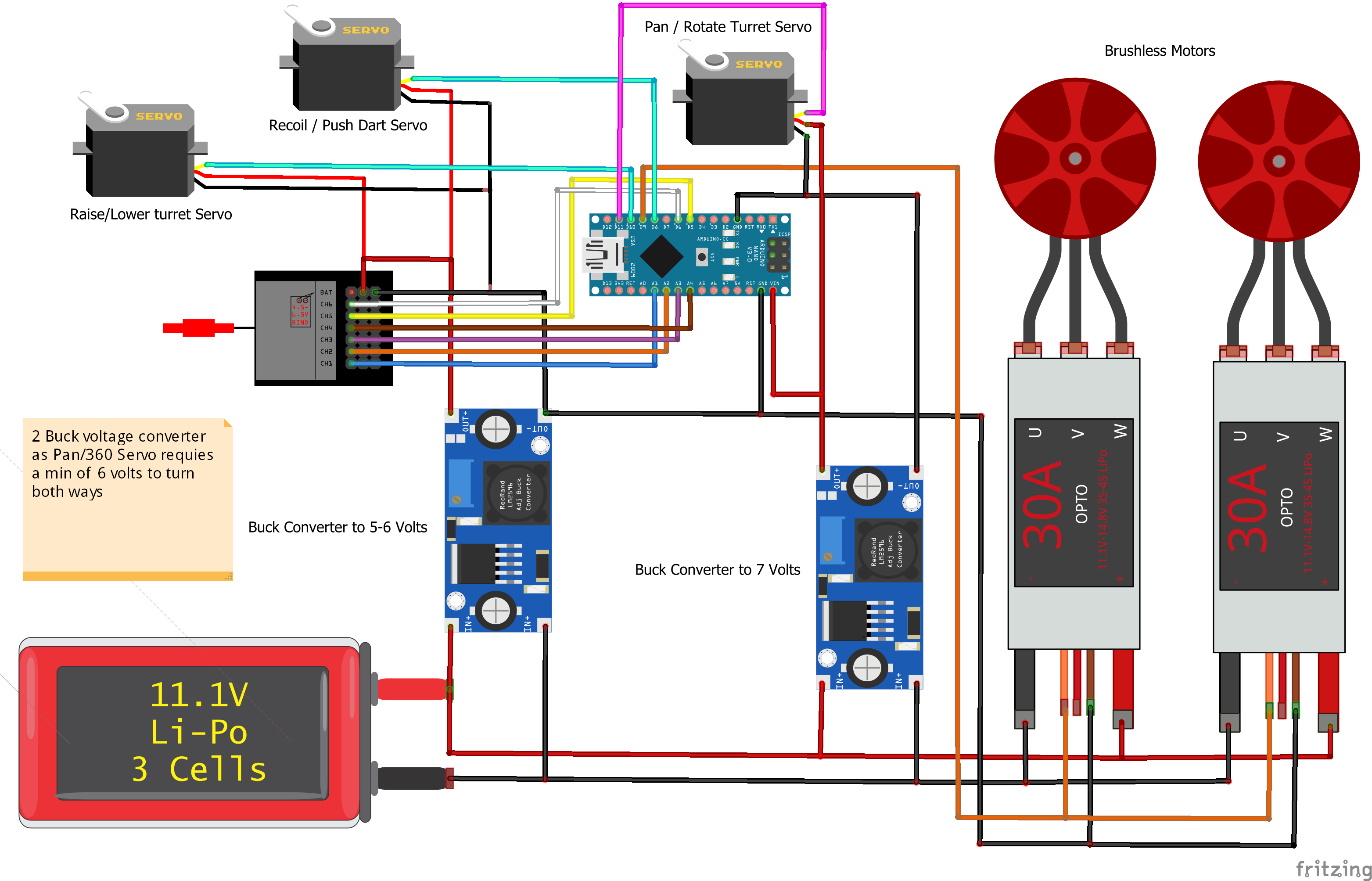
// Pan - Right Stick (left/right) Channel 1
// Turret Tilt - Left Stick (up/down) Channel 3
// VRA (left side) or switch SWA Channel 5
// VRB (right side) or switch SWD Channel 6
*/
///////////////////////////////////////////////////////////////
// Libraries used
///////////////////////////////////////////////////////////////
#include <Servo.h>
////////////////////////////////////////////////////////////////
// VARIABLES
////////////////////////////////////////////////////////////////
// Declared Servos
Servo pan_servo;
Servo tilt_servo;
Servo recoil_servo;
Servo flyWheels;
//Pins on Arduino connected to Servo signal pins
const byte pan_PIN = 11;
const byte tilt_PIN = 10;
const byte recoil_PIN = 8;
const byte flywheels_PIN = 9;
// Flywheels Spin-up speed
int flyWheel_speed = 1300;
const int StopFlywheels = 900;
boolean flywheels_ON = false; // Used to note is flywheels are spinning or not
// limits/positions/speed control for pan servo
const int pan_right = 1000; // Speed of servo to turn Turret Right (Clockwise most values under 1500)
const int pan_left = 2000; // Speed of servo to turn Turret Left (Counter-Clockwise most values over 1500)
int pan_LR_position = 0; // Variable used to limit/track how much the 360 servo turns left or right (not perfect)
const int pan_stop = 1484; // Value from reading PWM from RC transmitter center position to Serial monitor (use Serial Monitor to check value)
// limits for tilt (up & down) position of turret
const byte tilt_top = 40; // Angle of servo for fully extended/Top/raised turret position
const byte tilt_bottom = 140; // Angle of servo for lowest/Bottom/starting turret position
// boolean dart_pusher; // Turns ON or OFF automatic Dart pusher
const byte recoil_rest = 112; // Angle of the servo when at rest
const byte recoil_pushed = 48; // Angle the servo need to reach to push the dart
unsigned long currentTime = 0; // Used to set recoil timer
unsigned long previousTime = 0; // Used to set recoil timer
unsigned long recoilDelay = 1000; // Delay recoil start time and time between darts being fired (1000 = 1 Second)
/////// Smoothing for Tilt//////
// Define the number of samples to keep track of. The higher the number, the
// more the readings will be smoothed, but the slower the output will respond to
// the input. Using a constant rather than a normal variable lets us use this
// value to determine the size of the readings array.
const int numReadings = 5;
int readings[numReadings]; // the readings from the analog input
int readIndex = 0; // the index of the current reading
int total = 0; // the running total
int average = 0; // the average
// PWM input pins, any of the following pins can be used: digital 0 - 13 or analog A0 - A5
const int pwmPIN[] = {A2, A1, A3, A4, 5, 6}; // an array to identify the PWM input pins (first pin in array is channel 1, second is channel 2...etc)
int RC_inputs = 6; // The number of RC channels used
// GLOBAL PWM DECODE VARIABLES
const int num_ch = sizeof(pwmPIN) / sizeof(int); // calculate the number of input pins (or channels)
volatile int PW[num_ch]; // an array to store pulsewidth measurements
volatile boolean prev_pinState[num_ch]; // an array used to determine whether a pin has gone low-high or high-low
volatile unsigned long pciTime; // the time of the current pin change interrupt
volatile unsigned long pwmTimer[num_ch]; // an array to store the start time of each PWM pulse
volatile boolean pwmFlag[num_ch]; // flag whenever new data is available on each pin
volatile boolean RC_data_rdy; // flag when all RC receiver channels have received a new pulse
unsigned long pwmPeriod[num_ch]; // period, mirco sec, between two pulses on each pin
byte pwmPIN_reg[num_ch]; // each of the input pins expressed as a position on it's associated port register
byte pwmPIN_port[num_ch]; // identify which port each input pin belongs to (0 = PORTB, 1 = PORTC, 2 = PORTD)
////////////////////////////////////////////////////////////////
// FUNCTIONS to use/connect RC Controller/Transmiter
////////////////////////////////////////////////////////////////
// FUNCTION USED TO TURN ON THE INTERRUPTS ON THE RELEVANT PINS
void pciSetup(byte pin) {
*digitalPinToPCMSK(pin) |= bit (digitalPinToPCMSKbit(pin)); // enable pin
PCIFR |= bit (digitalPinToPCICRbit(pin)); // clear any outstanding interrupt
PCICR |= bit (digitalPinToPCICRbit(pin)); // enable interrupt for the group
}
// FUNCTION USED TO FIND THE PIN POSITION ON EACH PORT REGISTER: helps the interrupt service routines, ISR, run faster
void pwmPIN_to_port() {
for (int i = 0; i < num_ch; i++) {
// determine which port and therefore ISR (PCINT0_vect, PCINT1_vect or PCINT2_vect) each pwmPIN belongs to.
pwmPIN_port[i] = 1; // pin belongs to PCINT1_vect (PORT C)
if (pwmPIN[i] >= 0 && pwmPIN[i] <= 7) pwmPIN_port[i] = 2; // pin belongs to PCINT2_vect (PORT D)
else if (pwmPIN[i] >= 8 && pwmPIN[i] <= 13) pwmPIN_port[i] = 0; // pin belongs to PCINT0_vect (PORT B)
// covert the pin number (i.e. pin 11 or pin A0) to the pin position in the port register. There is most likely a better way of doing this using a macro...
// (Reading the pin state directly from the port registers speeds up the code in the ISR)
if (pwmPIN[i] == 0 || pwmPIN[i] == A0 || pwmPIN[i] == 8) pwmPIN_reg[i] = 0b00000001;
else if (pwmPIN[i] == 1 || pwmPIN[i] == A1 || pwmPIN[i] == 9) pwmPIN_reg[i] = 0b00000010;
else if (pwmPIN[i] == 2 || pwmPIN[i] == A2 || pwmPIN[i] == 10) pwmPIN_reg[i] = 0b00000100;
else if (pwmPIN[i] == 3 || pwmPIN[i] == A3 || pwmPIN[i] == 11) pwmPIN_reg[i] = 0b00001000;
else if (pwmPIN[i] == 4 || pwmPIN[i] == A4 || pwmPIN[i] == 12) pwmPIN_reg[i] = 0b00010000;
else if (pwmPIN[i] == 5 || pwmPIN[i] == A5 || pwmPIN[i] == 13) pwmPIN_reg[i] = 0b00100000;
else if (pwmPIN[i] == 6) pwmPIN_reg[i] = 0b01000000;
else if (pwmPIN[i] == 7) pwmPIN_reg[i] = 0b10000000;
}
}
// SETUP OF PIN CHANGE INTERRUPTS
void setup_pwmRead() {
for (int i = 0; i < num_ch; i++) { // run through each input pin
pciSetup(pwmPIN[i]); // enable pinchange interrupt for pin
}
pwmPIN_to_port(); // determines the port for each input pin
// pwmPIN_to_port() also coverts the pin number in pwmPIN[] (i.e. pin 11 or pin A0) to the pin position in the port register (i.e. 0b00000001) for use in the ISR.
if (RC_inputs == 0 || RC_inputs > num_ch) RC_inputs = num_ch; // define the number of pins connected to an RC receiver.
}
// READ INTERRUPTS ON PINS D8-D13: ISR routine detects which pin has changed, and returns PWM pulse width, and pulse repetition period.
ISR(PCINT0_vect) { // this function will run if a pin change is detected on portB
pciTime = micros(); // Record the time of the PIN change in microseconds
for (int i = 0; i < num_ch; i++) { // run through each of the channels
if (pwmPIN_port[i] == 0) { // if the current channel belongs to portB
if (prev_pinState[i] == 0 && PINB & pwmPIN_reg[i]) { // and the pin state has changed from LOW to HIGH (start of pulse)
prev_pinState[i] = 1; // record pin state
pwmPeriod[i] = pciTime - pwmTimer[i]; // calculate the time period, micro sec, between the current and previous pulse
pwmTimer[i] = pciTime; // record the start time of the current pulse
}
else if (prev_pinState[i] == 1 && !(PINB & pwmPIN_reg[i])) { // or the pin state has changed from HIGH to LOW (end of pulse)
prev_pinState[i] = 0; // record pin state
PW[i] = pciTime - pwmTimer[i]; // calculate the duration of the current pulse
pwmFlag[i] = HIGH; // flag that new data is available
if (i + 1 == RC_inputs) RC_data_rdy = HIGH;
}
}
}
}
// READ INTERRUPTS ON PINS A0-A5: ISR routine detects which pin has changed, and returns PWM pulse width, and pulse repetition period.
ISR(PCINT1_vect) { // this function will run if a pin change is detected on portC
pciTime = micros(); // Record the time of the PIN change in microseconds
for (int i = 0; i < num_ch; i++) { // run through each of the channels
if (pwmPIN_port[i] == 1) { // if the current channel belongs to portC
if (prev_pinState[i] == 0 && PINC & pwmPIN_reg[i]) { // and the pin state has changed from LOW to HIGH (start of pulse)
prev_pinState[i] = 1; // record pin state
pwmPeriod[i] = pciTime - pwmTimer[i]; // calculate the time period, micro sec, between the current and previous pulse
pwmTimer[i] = pciTime; // record the start time of the current pulse
}
else if (prev_pinState[i] == 1 && !(PINC & pwmPIN_reg[i])) { // or the pin state has changed from HIGH to LOW (end of pulse)
prev_pinState[i] = 0; // record pin state
PW[i] = pciTime - pwmTimer[i]; // calculate the duration of the current pulse
pwmFlag[i] = HIGH; // flag that new data is available
if (i + 1 == RC_inputs) RC_data_rdy = HIGH;
}
}
}
}
// READ INTERRUPTS ON PINS D0-7: ISR routine detects which pin has changed, and returns PWM pulse width, and pulse repetition period.
ISR(PCINT2_vect) { // this function will run if a pin change is detected on portD
pciTime = micros(); // Record the time of the PIN change in microseconds
for (int i = 0; i < num_ch; i++) { // run through each of the channels
if (pwmPIN_port[i] == 2) { // if the current channel belongs to portD
if (prev_pinState[i] == 0 && PIND & pwmPIN_reg[i]) { // and the pin state has changed from LOW to HIGH (start of pulse)
prev_pinState[i] = 1; // record pin state
pwmPeriod[i] = pciTime - pwmTimer[i]; // calculate the time period, micro sec, between the current and previous pulse
pwmTimer[i] = pciTime; // record the start time of the current pulse
}
else if (prev_pinState[i] == 1 && !(PIND & pwmPIN_reg[i])) { // or the pin state has changed from HIGH to LOW (end of pulse)
prev_pinState[i] = 0; // record pin state
PW[i] = pciTime - pwmTimer[i]; // calculate the duration of the current pulse
pwmFlag[i] = HIGH; // flag that new data is available
if (i + 1 == RC_inputs) RC_data_rdy = HIGH;
}
}
}
}
// RC OUTPUT FUNCTIONS
boolean RC_avail() {
boolean avail = RC_data_rdy;
RC_data_rdy = LOW; // reset the flag
return avail;
}
////// GENERIC PWM FUNCTIONS //////
unsigned long pin_time;
float pin_pwm;
float pin_period;
boolean PWM_read(int CH) {
if (CH < 1 && CH > num_ch) return false;
int i = CH - 1;
boolean avail = pwmFlag[i];
if (avail == HIGH) {
pwmFlag[i] = LOW;
noInterrupts();
pin_time = pwmTimer[i];
pin_pwm = PW[i];
pin_period = pwmPeriod[i];
interrupts();
}
return avail;
}
unsigned long PWM_time() {
return pin_time;
}
float PWM_period() {
return pin_period;
}
float PWM() {
return pin_pwm;
}
float PWM_freq() {
float freq;
return freq = 1000000 / pin_period; // frequency Hz
}
float PWM_duty() {
float duty;
duty = pin_pwm / pin_period;
return duty;
}
////////////////////////////////////////////////////////////////
// TURRET FUNCTIONS
////////////////////////////////////////////////////////////////
// Fires dart moving recoil servo
void dartFire() {
currentTime = millis();
if (flywheels_ON && currentTime - previousTime >= recoilDelay) { // Sets timer to recoil / fire dart every 1 sec if recoilDelay variable is set to 1000
recoil_servo.write(recoil_pushed);
delay (100);
recoil_servo.write(recoil_rest);
previousTime = currentTime; // Updates the time counter for the above (if) statement to work correctly
}
}
// Used to RC Switch position for dart firing / flywheels spinning / motors ON
void flyWheels_Switch () {
if (PWM_read(5)) { //Read PWM from Channel 5
int recoil_swtich_position = PWM();
recoil_swtich_position = map(recoil_swtich_position, 1030, 1960, 1000, 2000); // Map and Constrain calibrated servo values
recoil_swtich_position = constrain(recoil_swtich_position, 1000, 2000); // 1000=OFF 2000=ON
// Serial.println(recoil_swtich_position); // Prints recoil_swtich_position / PWM to Serial Monitor
if (recoil_swtich_position > 1500) { // if switch using channel 5 on transmiter is turned ON
flyWheels.writeMicroseconds(1400); // spin up flywheels to (speed) between 1000-2000 for brushless motors
delay (1000);
flywheels_ON = true;
dartFire(); // Starts recoil servo to fire dart
}
else {
recoil_servo.write(recoil_rest); // Puts recoil servo to back/default posistion
flywheels_ON = false;
flyWheels.writeMicroseconds(StopFlywheels); // Preset variable to 900 below the motor range to prevent twitching
}
}
}
// Function to move Turret Left or Right
void moveTurret () {
if (PWM_read(1)) { //Read PWM from Channel 1
int pan_servo_position = PWM();
// Serial.println(pan_servo_position); // Prints pan_servo_position / PWM to Serial Monitor
// Serial.println(pan_LR_position); // Prints pan_LR_position variable to Serial Monitor
if (pan_servo_position < 1400 && pan_LR_position > -15) { // limits the 360 servo rotation to the left
pan_LR_position = pan_LR_position - 1; // used to record left movement of the 360 servo
pan_servo.writeMicroseconds(pan_left);
}
else if (pan_servo_position > 1600 && pan_LR_position < 15) { // limits the 360 servo rotation to the right
pan_LR_position = pan_LR_position + 1; // used to record right movement of the 360 servo
pan_servo.writeMicroseconds(pan_right);
}
else {
pan_servo.writeMicroseconds(pan_stop);
}
}
}
// Function to move Turret up & down
void tiltTurret () {
if (PWM_read(3)) { //Read PWM from Channel 3
int tilt_servo_position = PWM();
tilt_servo_position = map(tilt_servo_position, 1020, 1960, tilt_bottom, tilt_top); // Map (first value mapped is used as the default position) and Constrain calibrated servo values
tilt_servo_position = constrain(tilt_servo_position, tilt_top, tilt_bottom);
// Serial.println(tilt_servo_position); // Prints tilt value to Serial Monitor 140=turret DOWN position 40=turret UP position
total = total - readings[readIndex]; // subtract the last reading
readings[readIndex] = tilt_servo_position; // read tilt position
total = total + readings[readIndex]; // add the reading to the total
readIndex = readIndex + 1; // advance to the next position in the array
if (readIndex >= numReadings) { // if we're at the end of the array...
readIndex = 0; // ...wrap around to the beginning:
}
average = total / numReadings; // calculate the average:
// Serial.println(average); // Print average reading to Serial Monitor
delay(1); // delay in between reads for stability
tilt_servo.write(average); // Writes average position for servo to help prevent servo twitching
}
}
///////////////////////////////////////////////////
// SETUP - test
///////////////////////////////////////////////////
void setup()
{
// Serial.begin(9600); // begin serial communication
// initialize all the readings to 0:
for (int thisReading = 0; thisReading < numReadings; thisReading++) {
readings[thisReading] = 0;
}
setup_pwmRead();
// Attach Flywheel motors to pins
flyWheels.attach(flywheels_PIN); // ESC setup to Ardiuno PIN
tilt_servo.write(tilt_bottom); // Sets default turret position
recoil_servo.write(recoil_rest);
//-----attaches servo to pins
pan_servo.attach(pan_PIN, 1000, 2000); // Sets range of PWM when attaching servo to pin
tilt_servo.attach(tilt_PIN);
recoil_servo.attach(recoil_PIN);
}
///////////////////////////////////////////////////
// LOOP
///////////////////////////////////////////////////
void loop() {
moveTurret ();
tiltTurret ();
flyWheels_Switch ();
}


Comments
Please log in or sign up to comment.