If you made the wise choice of having kids in your life, eventually you will face the situation that they are losing their cuteness and fun factor over time. As the teenage years stretch into young adulthood, they tend to listen less to you and consume more internet bandwidth. Maybe I was too soft in my educational practices but I will not discuss that here for now. My actual problem is that the young adults in the house are making poor life choices by playing video games late into the night and end up being more tired for school and work, and also more irritable. I use to have severe rules in the firewall with MAC addresses control etc, but over time with too many requests for late extension when there is exams and long university homework etc, I eventually got tired of the router military management. I capitulated and took the “they are grown up now” approach and disabled parental control.
However, still being a caring dad, when I wake up late at night I can hear some subtle noises (these kids can be sneaky) that alert me that there is probably a substantial stream of gaming packets travelling in “my” home network. So what I do is take my iPad that rests on my night table , connect to the web interface of the router and reboot it. Usually within seconds there is less subtle noises (chairs moving, mouse banging etc) confirming my suspicions. Most of the time I will reboot it three times in a row to discourage the more tenacious. Eventually I can hear bathroom noises, spring mattress squeaks an eventually a real quiet house. And this brings us to the real heart of the problem; after that 5-10 minutes of blue light from the iPad and all the required brain activity, I am now in a mental state where it is more easy to begin thinking about my next day at work than it is to fall back asleep.
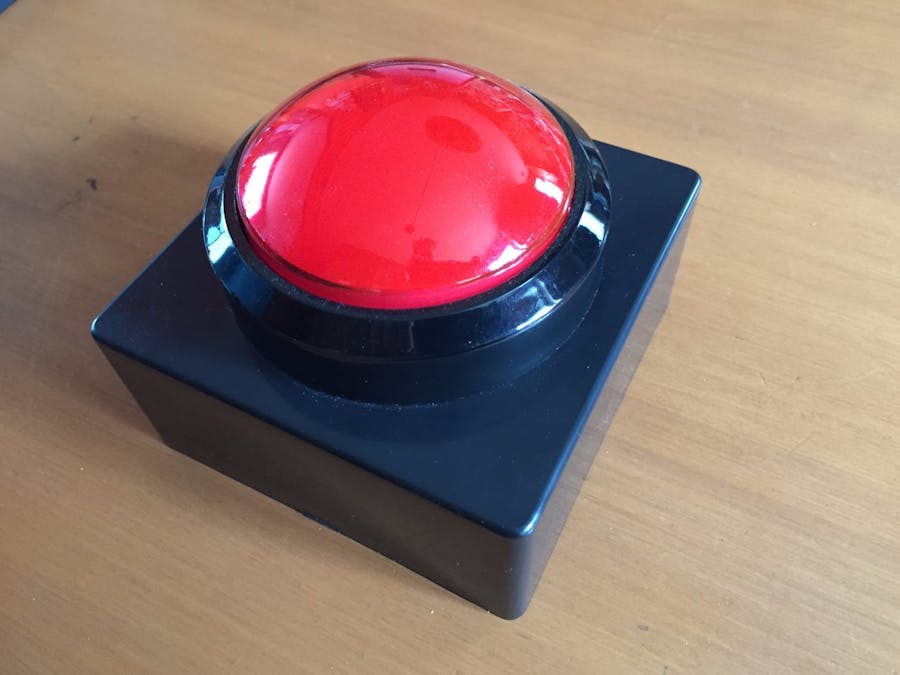
The solutionA big button on the night table that I can just hit and then roll over back to sleep.
Requirements
- batteries; (please not another wall adapter)
- no wires (wifi)
- cheap (no raspberry pi)
- simple (easy and fast to build)
Feasibility
My biggest question was if I could easily tell the router to reboot from another system. After some searches about uPNP, remote reboot etc, I realized that I had no other choices than logging into the router in one way or another. Since I did not want to have to understand the whole router administration web interface (Just quickly looking at the pages code steered me away). So I went the telnet way; on my router the telnet server is not enabled by default , there is a toggle in the administration interface. After that, for security reasons, I just wanted to make sure that the telnet server was not reachable from the WAN (internet) side. I could not find a definite textual answer from all my searches. So I did some testing myself and found out that, as I thought, it is not visible from the outside of my network. I would never have left a telnet server to my router on the open internet. With a telnet server enabled in the router, it is pretty easy to log in and send a reboot command just by sending some text.
Hardware Platform
My platform choice went to the esp8266 (http://makezine.com/2015/04/01/esp8266-5-microcontroller-wi-fi-now-arduino-compatible/) ; it is very cheap and should be versatile enough to handle all the requirements of this project. I got the Huzzah board from Adafruit which provided me with an esp8266 mounted with a voltage regulator some leds and switches. It is also preprogrammed with the NodeMCU firmware which greatly simplify the programming of the board by using LUA as the scripting language.
Limitations
If your router does not support telnet and only support ssh connection, you will need a system that is powerful enough to do crypto stuff (like a ssh client) this would bring us in the realm of the raspberry pi etc (full computer/os) and would considerably increase the price and complexity of this project.
If your router only support the web interface, you need a platform that can do http but most importantly you need to look at the code of your router administration pages to understand the type of http request you will need to send the router to force a reboot. Here we fall into light to moderate reverse engineering. To me, this would remove the easy/fun aspect of this project. Keep in mind that if you go that route, the platform chosen in this project (esp8266/NodeMCU) can handle http communication.
How does it work ?Usage
- When you press the button you activate the auto cutoff circuitry which will begin to power the huzzah board for a period of time long enough to perform the five reboots sequence.
- If the button flashes very rapidly, that means that the batteries are too low and it is time to replace them. The reboot sequence will not happen.
- The button flashes slowly to indicate that it is not connected to the router.
- Our Huzzah will try to connect to the wifi network.
- Once connected it will stop flashing.
- It opens a telnet connection with the router and send credentials.
- Once authenticated it sends the reboot command
- The router reboots; the Huzzah gets disconnected and start flashing again to indicate that it is disconnected.
- Wait a minute and try to reconnect to the wifi.
- Once connected again, repeat four sequences of reboot
- After last reboot, send the Huzzah to sleep to save power during the remaining powered phase
- Power gets cut by the auto shutoff circuit
Circuit
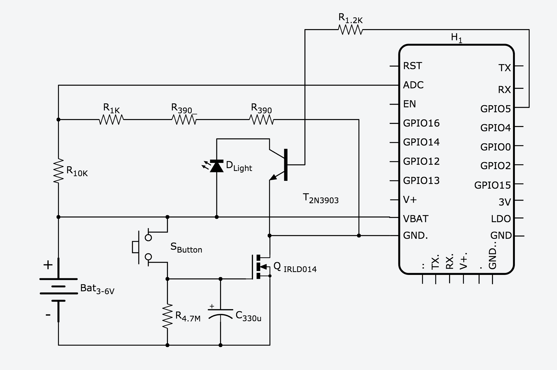
Since we are using batteries, we need some sort of cutoff mechanism to save energy while not in use. To simplify the design of the firmware code, I decided to go with a very simple external auto shutoff circuit instead of using the controller power management (deep sleep etc). This is what the 4.7M resistor, 330uF capacitor and the MOSFET transistor are for. Once you press the button, the circuit will be fed by the batteries for 7-8 minutes which is plenty of time to reboot five consecutive times. You can play with the values of the resistor and capacitor if you want to change the “Up” time. Because of this design, you need to wait that the auto shutoff circuit has cut the power (~8 minutes) before you could reuse the button; otherwise just repressing the button before the end will not reset the circuit, it will just keep the power up for another 8 minutes. This is a minor flaw of that circuit but like I said before; I wanted to keep it simple. The 2n3903 transistor and 1.2K resistor are for driving the led of the button with the low power GPIO of the Huzzah. The four resistors (390, 390, 1K, 10K) make a voltage divider for the batteries to feed the ADC of the Huzzah. This is our low voltage detector. The light is included in the assembly of the pushbutton and there is already a resistor built in so there is no need to protect that led with an extra one and we feed it directly with the battery. You can power that circuit with 3 or 4 AA batteries. 4 batteries will give you a brighter button and longer battery life.
Firmware
The firmware code for this project (Lua scripts) is available in the following BitBucket repository : https://bitbucket.org/jmjulien/routerrebootbutton It is made out of four files :
- init.lua
- credentials.lua
- main.lua
- network.lua
I did try to over comment the code so it is self explanatory even for a newcomer to the platform. You will need to modify the credentials.lua script to update it with your credentials to connect in your wifi network and the administrator username/password to log into your router by telnet. You also might need a different sequence of character to reboot your router. For my router, the command is “reboot”. Just connect to your router manually with a telnet console and figure out what text command does the trick. Most probably it will be “reboot”. However some router have a small text menu and you might just need to send a number. You also need to set the various text to search in the replies of your router so the code knows when to send the various commands. Again these are quit easy to figure out by logging manually in the router and looking at the interactions. Here is what my router telnet sequence looks like:
So my search words are :
SEARCH_USER = "login"
SEARCH_PWD = "Password"
SEARCH_PROMPT = "#"
It can be any text that is unique to the line that we are expecting; like for the prompt , i’m just waiting for “#” as this does only appear when the router is ready to receive a command.
Keep in mind that this is case sensitive; in my case, “Password" begins with a capital P.
In network.lua there is two values (reboot_count, reboot_period) that you can adjust if you want to change the behaviour of the system. You could change the count to 1 if you just want a remote router reboot button.
WARNING: Adafruit has issued a errata that the pin 5 and 4 are inverted on some versions of the Huzzah. Mine were, so the firmware is adjusted for that. If they are not on yours, just change BUTTON_LED_PIN to 2 instead of 1 in the script init.lua.
NOTE: The Adafruit Huzzah is delivered with "NodeMCU 0.9.5” so the firmware is coded to support this older version. If you look at the NodeMCU online documentation you might find some discrepancies with the way I made some parts of the code. This was necessary since that "the new way" of doing some things are not available in this older version. If you upgrade NodeMCU to the latest version on your board, you might need to fiddle with the code.
The BuildParts
- Huzzah 10$ (https://www.adafruit.com/product/2471)
- Big button 10$ (https://www.adafruit.com/products/1185)
- Battery holder 3-4 AAA 3$
- Project Box , big and deep enough to hold the switch button 5$ (Hammond 1591USBK)
- Perforated generic project PCB 1$
- MOSFet transistor IRLD014 1$
- capacitor 330uF .50$
- transistor 2n3903 or 2n3904 .25$
- resistors 390, 390, 1K, 10K, 1.2K, 4.7M 1$
Price total -> 25$ - 30$
To program the board, you will need a FTDI cable(Any OS) or a USB-serial cable (Windows only). The FTDI cable is more expensive (15-20$) but is a good investment if you play with various microcontroller boards.
Assembly
Connect the components by following the diagram. I did use a small generic perforated circuit board to cleanly connect the electronic components together.
This is a small circuit so it is not very complicated.
Drill a hole in the centre of the cover of the project box to hold the pushbutton.
Connect the button and the battery holder to the circuit board with small wires.
Programming
Using a usb to serial cable, and one of the development tool recommended in the NodeMCU documentation, program the Huzzah board with the firmware files mentioned earlier. Just upload the four lua files on the board. You should load init.lua last as it is the one that invokes all the other ones. https://nodemcu.readthedocs.io/en/master/en/upload/
I personally like ESPlorer, but nodemcu_uploader.py works well too.
ConclusionIt is always sweet at the dinner table to learn from some house residents that we might be afflicted with internet connectivity issues; but no specific examples to describe. I love these kids.


_3u05Tpwasz.png?auto=compress%2Cformat&w=40&h=40&fit=fillmax&bg=fff&dpr=2)
Comments
Please log in or sign up to comment.