


Hardware components | ||||||
| × | 1 | ||||
 |
| × | 1 | |||
| × | 1 | ||||
 |
| × | 1 | |||
_baVEVgguW1.jpg?auto=compress%2Cformat&w=48&h=48&fit=fill&bg=ffffff) |
| × | 1 | |||
Software apps and online services | ||||||
 |
| |||||
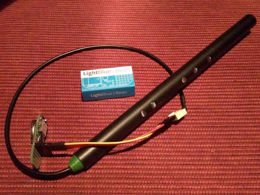
The OpenPipe Breakout from openpipe.cc is a 3D-printed bagpipe chanter with capacitive finger sensors. This project joins the OpenPipe Breakout with the BLE MIDI capable LightBlue Bean to create wireless bagpipes.
Assembly is TrivialBegin by connecting the wires from the pipe cable to pins A0, A1, D0 and D1 on the LightBlue Bean. In the image above, the wires are connected to an 8-pin female header soldered to the bean.
- RED => D0 (VCC)
- BLACK => D1 (GND)
- WHITE => A0 (SDA)
- GREEN => A1 (SCL)
The four short wires shown below serve to connect the wires from the pipe cable to their destination on the bean. The half braid swaps the left pair of wires with the right pair.
The remaining steps are to upload the sketch, establish a BLE MIDI connection to the pipe from your favorite music app, and then start playing!
To upload the sketch you'll need the standalone Arduino IDE and Punch Through Design's CLI Loader. These tools are used instead of the more convenient web-based ones because there is currently no way to import OpenPipe's custom library into Punch Through Design's compiler in the cloud.
For playing the pipe I recommend using ThumbJam or Universal Piper on an iOS device. ThumbJam supports BLE MIDI connections. For apps such as Universal Piper that do not, the midimittr app can act as the intermediary.
Connecting to other boardsTo use the OpenPipe Breakout with a different board, follow the connection guide for your board below and upload the matching sketch.
Adafruit Feather nRF52
- RED => 27 (VCC)
- BLACK => 30 (GND)
- WHITE => 25 (SDA)
- GREEN => 26 (SCL)
NOTE: The Adafruit Feather nRF52 needs external pull-up resistors (4k7) on SDA and SCL, as shown in the photo below.
Arduino 101
- RED => A2 (VCC)
- BLACK => A3 (GND)
- WHITE => A4 (SDA)
- GREEN => A5 (SCL)
LightBlue Bean+
On the LightBlue Bean+ you can use pins A2 through A5, same as Arduino 101 above.
Another option shown below is to use the I2C Grove connector. This provides a sturdy, low profile connection that frees up pins A2 and A3 for some other use.
The left two pins of the I2C Grove connector are GND and VCC, and the right two pins are A4 and A5. Since the connector already provides power, the line of code that configures power and ground on A2 and A3 can be commented out:
//OpenPipe.power(A2, A3);
SparkFun nRF52 Breakout
- RED => 22 (VCC)
- BLACK => 23 (GND)
- WHITE => 24 (SDA)
- GREEN => 25 (SCL)
NOTE: The SDA and SCL assignments must be redefined in the SparkFun variants.h file. For more details see this hookup guide discussion.


_3u05Tpwasz.png?auto=compress%2Cformat&w=40&h=40&fit=fillmax&bg=fff&dpr=2)
Comments
Please log in or sign up to comment.