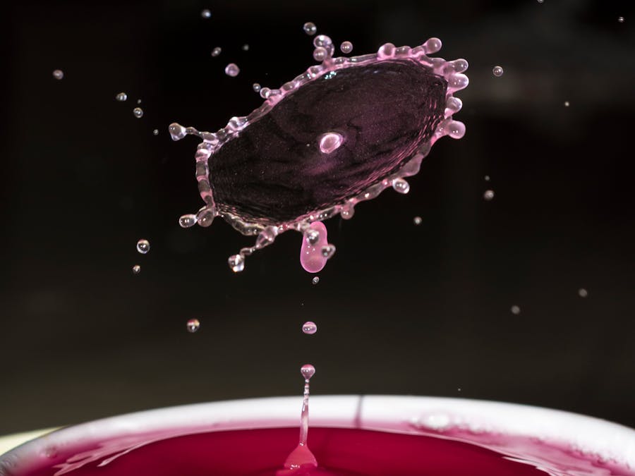
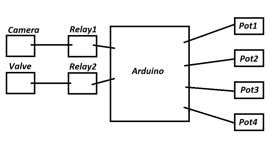
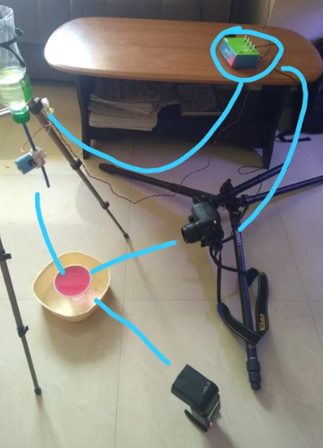
Water drop photography requires two (or more) water drops of controlled size to be dropped one after the other at precise timing. It also requires the camera to be triggured at a time when the bounce of first drop collides with the second drop and splashes.
It is insane to get a repetitive result to do all these manually and of course not willing to spend money to buy it from market!
So I deceided to make one using Arduino.....
/*

POT1 >> DELAY of SIZE of DROP1
POT2 >> DELAY for DROP2
POT3 >> DELAY of SIZE of DROP2
POT4 >> DELAY for CAMERA TRIGER from END OF D1

*/


int potPin1 = 0;    // select the input pin for the potentiometer
int potPin2 = 1;    // select the input pin for the potentiometer
int potPin3 = 2;    // select the input pin for the potentiometer
int potPin4 = 3;    // select the input pin for the potentiometer
int ValvePin = 8;   // select the pin for the Valve
int CameraPin = 9;  // to trigger camera
int TriggerPin = 2; // Swith trigger

int LEDRed = 6;
int LEDGreen = 7;

int d1, d2, d3, d4;  // Delay values of each POT's
int d1m, d2m, d3m, d4m;   //Max delay corresponding full scale of POT (1023)

float pm = 1023.0;


void setup() {

  Serial.begin(9600);


  //Setting Pin Modes
  pinMode(potPin1, INPUT);  // declare the PotPin as an INPUT
  pinMode(potPin2, INPUT);  // declare the PotPin as an INPUT
  pinMode(potPin3, INPUT);  // declare the PotPin as an INPUT
  pinMode(potPin4, INPUT);  // declare the PotPin as an INPUT
  pinMode(ValvePin, OUTPUT);  // declare the ValvePin as an OUTPUT
  pinMode(CameraPin, OUTPUT);  // declare the CameraPin as an OUTPUT
  pinMode(TriggerPin, INPUT_PULLUP); // For the Switch


  pinMode(LEDRed, OUTPUT);  // declare LED Red
  pinMode(LEDGreen, OUTPUT);  // declare LED Green


  // intializing.....

  // Max of each Pot
  d1m = 150;
  d2m = 500;
  d3m = 150;
  d4m = 500;

  // Set valve, camera, LED pins low
  digitalWrite(ValvePin, HIGH);
  digitalWrite(CameraPin, HIGH);

  LED_Set(0);

}

void loop() {


  if ( digitalRead(TriggerPin) == LOW ) {


    // turn LED RED
    LED_Set(-1);
    delay(1000);

    // Read Pot positions and set delays
    d1 = (analogRead(potPin1) / pm) * d1m ;
    d2 = (analogRead(potPin2) / pm) * d2m ;
    d3 = (analogRead(potPin3) / pm) * d3m ;
    d4 = (analogRead(potPin4) / pm) * d4m ;
    d4 = d4 - d2 - d3;


    //STARTING LOOP ****************************

    //first drop
    LED_Set(1);   // turn LED GREEN
    digitalWrite(ValvePin, LOW);  // turn the Valve on
    delay(d1);
    digitalWrite(ValvePin, HIGH);  // turn the Valve off
    LED_Set(-1);   // turn LED RED
    // first drop complete


    //waiting for GAP for Drop 2
    delay(d2);


    //second drop

    LED_Set(1);   // turn LED GREEN
    digitalWrite(ValvePin, LOW);  // turn the Valve on
    delay(d3);
    digitalWrite(ValvePin, HIGH);  // turn the Valve off
    LED_Set(-1);   // turn LED RED
    //second drop complete


    //waiting for camera trigerring
    if (d4 >=0) {
      delay(d4);

      //trigger camera
      LED_Set(1);   // turn LED GREEN
      digitalWrite(CameraPin, LOW);  // turn the Valve on
      delay(200);
      digitalWrite(CameraPin, HIGH);  // turn the Valve off
      delay(100);                       // for seeing LED
      LED_Set(-1);   // turn LED RED

    }


    // turn OFF Switch LED
    delay(100);
    LED_Set(0);   // turn LED OFF

  }


}


void LED_Set(int LEDColor) {

  // LEDColor : -1 > RED | 0 > OFF | 1 > GREEN

  Serial.println(LEDColor);

  if (LEDColor == -1) {
    digitalWrite(LEDGreen, LOW);
    digitalWrite(LEDRed, HIGH);
  } else if (LEDColor == 0) {
    digitalWrite(LEDRed, LOW);
    digitalWrite(LEDGreen, LOW);
  } else if (LEDColor == 1) {
    digitalWrite(LEDRed, LOW);
    digitalWrite(LEDGreen, HIGH);
  }


}


Comments
Please log in or sign up to comment.