


Hardware components | ||||||
 |
| × | 2 | |||
 |
| × | 1 | |||
Software apps and online services | ||||||
| ||||||
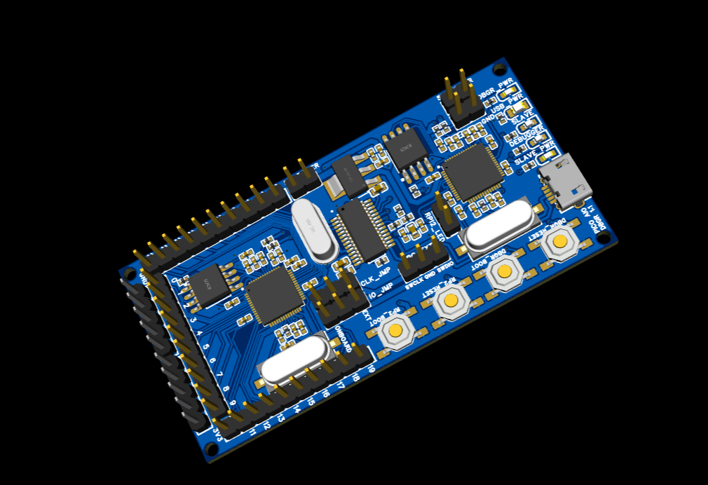
As you debug with a raspberry pi pico, things on the desk can get messy and confusing quick. To cut down on having to use two raspberry pi picos, I have created a board that implements them. One pico is a debugger and the other is the slave. The slave exposes all the GPIO pins, along with a few 3v3, GND, and 5v pins. There are 4 buttons, a set for each pico that allows you to reset and hold down the boot button; for programming. And to make things better, an onboard USB controller is implemented to remove the need for a USB port per each RP2040.
If you want to program an external pico board or rp2040 device, you can set two jumpers that allow you to use a set of SWD pins. This will remove the slave pico from being debugged and allow the external device to be debugged.
A jumper for the slave GPIO25 pin is onboard that hooks it up to an LED like a regular pico board does. If you want to use that pin for another reason, you can remove the jumper to break the connection to the LED.
5 LED are on board, Debugger Power, USB power, Slave Power, Debugger 25 pin, and slave 25 pin.
I plan on selling these dev boards on amazon for a few dollars to help other devs. They will be listed under the PICO AIO Debug board


Comments
Please log in or sign up to comment.