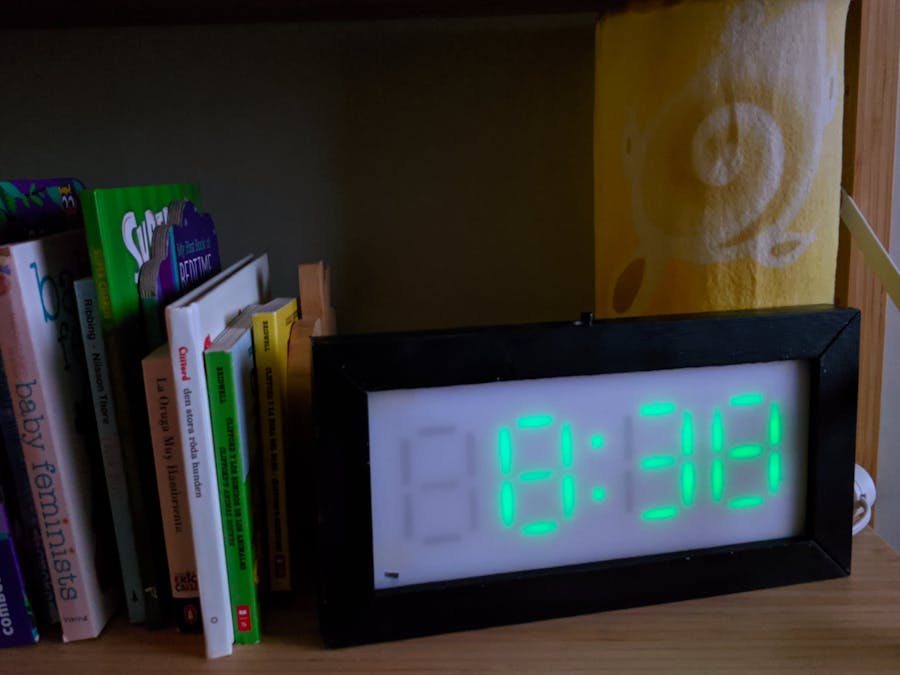
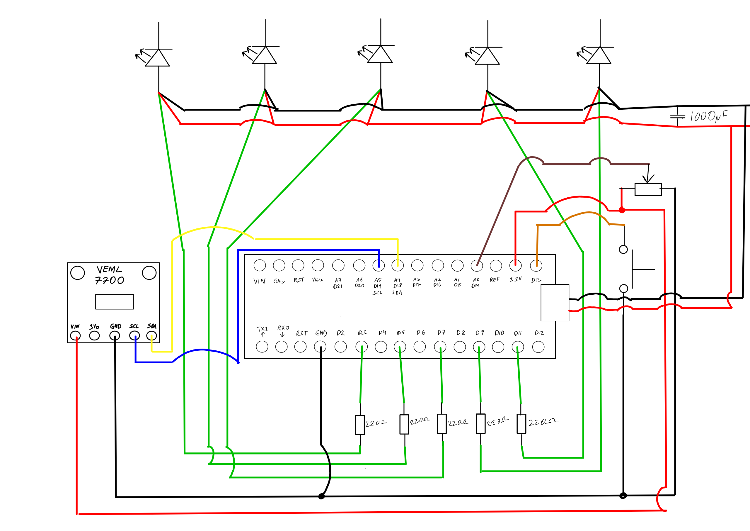
Small children have a tendency to wake up in the middle of the night or very early in the morning. Unfortunately at this age, they also usually haven’t learned how to tell time. So, I needed a way of helping the smol humans to know if it is still sleep time or not when they wake up. Someone told me about a clock that changes colour at night, to indicate that it is in fact night. But, instead of looking further into that and possibly buying one, I figured it would be much more fun to make one.
OperationPlug the adaptor in a wall socket and the clock will start up. Initially the clock will try to connect to the WiFi that was defined when uploading the code to the main board. During this time the separator LEDs will alternate between shining red and blinking blue. Once a WiFi connection has been established the time will be updated through NTP and displayed on the clock. That's it...
See below for more details regarding settings and additional features.
FeaturesIt’s a clock. It tells time (24 hours).
But, since the aim was to have a clock that changes colour when it’s night it also does that. The clock face is green during the day and red during the night. By default the time interval for night time is 18:30 to 6:45 (because that’s what fits my everyday life), but this can be changed (see below).
The push button and the potentiometer can be used to change clock state and settings.
The light sensor will make sure that the clock face is bright or dark enough for the surrounding light.
Push buttonLEDs on
- 1 short click - Turn off LEDs.
- 2 fast clicks - Activate day mode if night mode is active (see below).
- Long press, 2 seconds - Activates night mode if day mode is active (see below).
- Long press, 4 seconds - Activates night time interval setup (see below).
LEDs off
- 1 short click - Turn on LEDs.
- 2 fast clicks - Activate light sensor mode (see below).
- Long press, 2 seconds - Activates party mode (see below).
In night time interval setup mode the potentiometer is used to change the time.
Switching between day and night modeIt is possible to change between day and night mode outside of the set interval.
When day mode is active and the LEDs are on, press and hold the push button for 2 seconds. The separator LEDs will turn red and if the push button is released at this time night time mode will be activated.
If night mode is active and the LEDs are on, double click the push button and day mode will be activated. Useful if the smol human in question has woken up shortly before the night time interval is set to end and they want to get out of bed.
Night time setupIf the push button is pressed and held for 4 seconds (while the LEDs are on), the separator LEDs will turn blue. If the button is released at this time the night time setup mode will activate. The start time for the interval will be shown on the clock face and the hour digits will start flashing. Use the potentiometer to change the time and push the button to set. Once both a start and end time has been set for the night time mode, double-click the push button to save the new interval to the flash storage. Since the flash storage is used for this setting it will be kept even if power is lost to the clock.
Night time setup mode can be canceled by holding the push button for 2 seconds, until the separator LEDs turn blue.
Light sensor mode (dev setting)To help with tweaking the code for the light sensor I implemented a light sensing mode. It's not necessary for daily use of the clock but I decided to keep it in the code anyway. It’s not set to the highest possible resolution, I’ve instead picked a happy medium. It can of course be changed to accomodate better resolution or higher maximum possible lux values (see the linked docs below).
With the LEDs off, double-click the push button to activate this mode. The current calculated lux value from the light sensor will be displayed on the clock face. If a value higher than 9999 is recorded only dashes will be displayed. If a value less than 100 is recorded the value will be displayed with two decimal places, using the lower separator LED as a decimal point.
Double-clicking the push button again will end the light sensor mode.
See here for docs on how the light sensor is configured for an application: https://www.vishay.com/docs/84323/designingveml7700.pdf
Party TimeIf the LEDs are off, and the push button is held for 2 seconds the Party Time mode will activate. This will randomly pick one of three rainbow patterns that is displayed on the clock face for 30 seconds.
The patterns are:
- Change each LED’s colour continuously and randomly.
- The rainbow colours travel across the clock face from right to left.
- All LEDs cycle through the rainbow colours simultaneously.
Party Time mode can be canceled by double clicking the push button.
Persistent settings storageNight time interval settings are persistent. This is achieved by saving these to the flash storage (since the Arduino Nano 33 IoT lacks an EEPROM).
Using the board’s flash memory has some implications though, mainly that repeated writing to a flash storage will damage it. Generally it is recommended to keep the number of writes to a flash storage to less than 10000, so with any normal use of the clock this should not be an issue.
DesignInitially I only had two criteria: green during the day, red during the night.
InputWhile planning this project I also realised I needed a way to easily change settings, whichever they may be. For this I settled on a push button and a potentiometer.
The button can be multipurpose with different amounts of clicks and long presses and the potentiometer can be used to change whatever setting as needed. This way a potentially large number of settings and features can be controlled with only these two input controls. The potentiometer is attached by having a wooden plug pressing on the back of it from the front lid.
To be able to control each separate segment of the digits I needed to divide the case into individual chambers for each LED. For this I initially had several ideas, for example using a hand-held router on a wooden board to make chambers and wire paths. This would have been tricky to do by hand though (I would love owning a CNC machine, maybe I’ll build one someday), so I needed to explore other options. A 3D-printer would have made this very easy, but unfortunately that is not something I have access to (maybe someday I’ll afford one, or even build one myself).
What I eventually settled on was using a 15x2 mm aluminium flat bar to create a number of interlocking pieces to construct the chambers. I could also have used pieces of plastic to do the same, for example an opaque plastic can, but I enjoy working with aluminium and it would work as reflectors (somewhat) to help spread the light from the LEDs. Some of the aluminium pieces have notches cut out from the bottom to make space for the wiring and also to hold the wires in place. Important to note that aluminium is a good electrical conductor, so care needs to be taken so that no short circuits are created. Most of the time this is not an issue with an aluminium flat bar like this, since it’s anodised and that makes for a lousy conductive surface, but as soon as an end has been cut or a side has been filed down there is a bare surface of material with high conductivity. Making sure that none of these touch any bare wire or solder joints wasn’t much of an issue though.
For the clock face I figured I’d use a piece of semi-transparent plastic (from a plastic can) and mask out the digits by covering the back with paper and cutting out strips for the digit segments. I was worried that the single LED I would use for each segment would become too much of a hot spot against the plastic, so I also added a piece of baking paper to diffuse the light. To spread the light even further I decided to lastly add a piece of aluminium foil as a reflector that would help in spreading the light a little bit more inside the LED chamber. If needed I could also have added more aluminium foil to the sides and the bottom of the LED chambers, but in the end that turned out to not be needed.
The sheets of paper and aluminium are attached to each other with glue stick and then attached to the plastic piece with some rolled up (sticky side out) masking tape (double-sided tape would have been ideal, but not something I had at home at the moment).
It is also important that the light sensor can get enough light to control the LED brightness, so for this I cut out some space for it on the back of the plastic front piece and also made a shallow chamfer on the front to make as much of the sensor as possible to be exposed to light at the front of the clock.
The front panel is attached to the clock with a few screws from the back of the clock.


Comments
Please log in or sign up to comment.