For around $25, you can purchase a 60W constant current electronic load from sites like eBay, AliExpress or Banggood. They come as a pre-built unit without a case.
Some sites do sell a complete unit with a case for around $60 and of course as this is quite a popular electronic load, there are various home-made cases.
The problem with designing a case is the display board contains components of differing heights so it makes it hard to create a flat front panel.
The display board that came with my unit was poorly manufactured. The 7-segment displays are soldered in crooked. I thought about trying to unsolder them and re-soldering them so that they are parallel to each other and the edge of the board but that might mean that I could destroy the through hole plating in the process thus rendering the board useless. As the display board is pretty simplistic, I decided to reverse engineer it and make my own replacement.
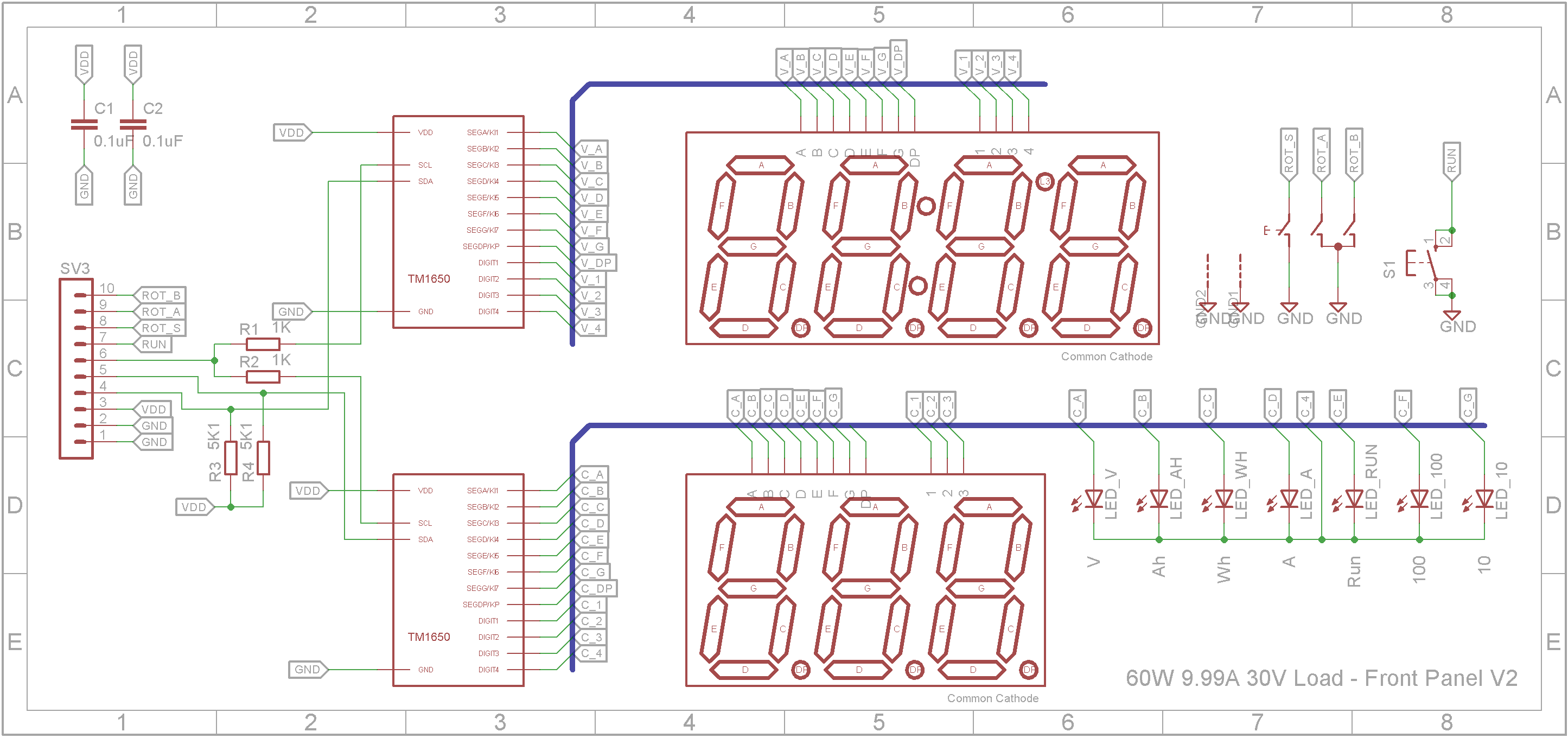
SchematicThe display board uses two 4-Digit I2C 7-Segment driver ICs. (TM1650). The 4th digit of the TM1650 for the 3-Digit display is used to drive the 7 individual LEDs on the board.
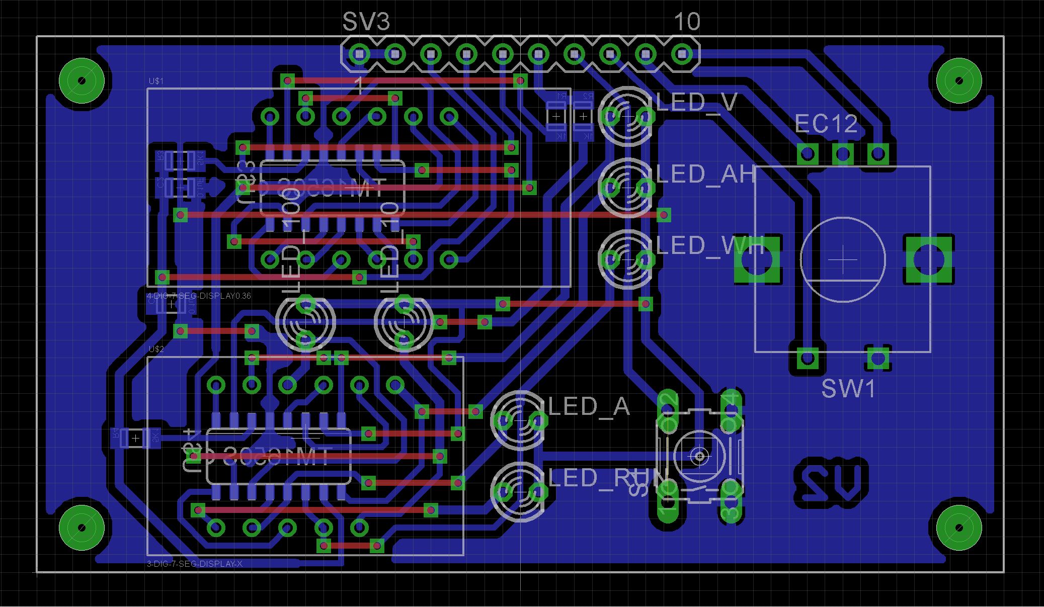
Because I was going to make my own PCB using the Toner method, I designed the board to be single sided. The layout is NOT identical to the display board that came with the unit itself.
The STL files are included. Either take these to a 3D print shop or if you have your own printer, run them through your slicing software. I used a 0.2mm layer height and they need orientating in your slicing software.
On the base and front panel, drill out the PCB mounting holes with a 2.5mm drill and create a thread with a 3mm tap.
The lugs that hold the shells together are a bit fragile. I glued on washers before I drilled the holes with a 2.5mm drill and created a thread with a 3mm tap. Drill out the holes that the screws go through with a 3mm drill.
The Eagle files are included in case you want to get the board commercially made or you can make it yourself. I used the Toner method to make mine.
Start by adding the SMD components. I find it easier to use solder paste rather than use solder from a reel when soldering SMD components.
Add the links if your board is single sided.
Next add the 10 pin header. If you use a header on a single sided board, here is the method I use to add them.
Place header on PCB with longer pin side down, solder pins, push black plastic down towards the PCB.
Now add the two 7-segment displays, push switch (with 12mm shaft + button top) and rotary encoder. Do not solder the individual LEDs yet. Instead, place the LEDs into their respective holes ensuring their orientation is correct and screw the PCB onto its mounts using four 6mm M3 screws.
Push each LED down hard against the front panel. The LED hole is countersunk so the LED should center itself against the front panel. Once done solder it in place and clip off any extra leads. Repeat this process on all 7 LEDs.
Fit the back panel over the fan. The hole may need some filing if the fit is too tight. Also add the DC power socket. I soldered the supply wires directly on the underside of the DC power socket on the main board. Make sure you get the polarity correct. Also connect two 10A cables to the screw terminal. These will go to the banana sockets on the front panel. Finally screw the board to the bottom of the case using six 6mm M3 screws.
You will need a 10 wire cable with a male Dupont header at one end and a female Dupont header at the other end to connect the display board to the main board. You can buy 10cm male-female Dupont cables on eBay if you don't want to make your own.
When I tested the unit, the rotary encoder was backward even though the wiring matched the original. The fix was simple enough, I just reversed the two encoder wires going down to the main PCB.
The unit operates as advertised and is a great tool for the toolbox. I was disappointed with the manufacturing quality of the front display when it arrived. With a replacement display board, the unit certainly looks the part and I am happy with the results overall.


Comments
Please log in or sign up to comment.