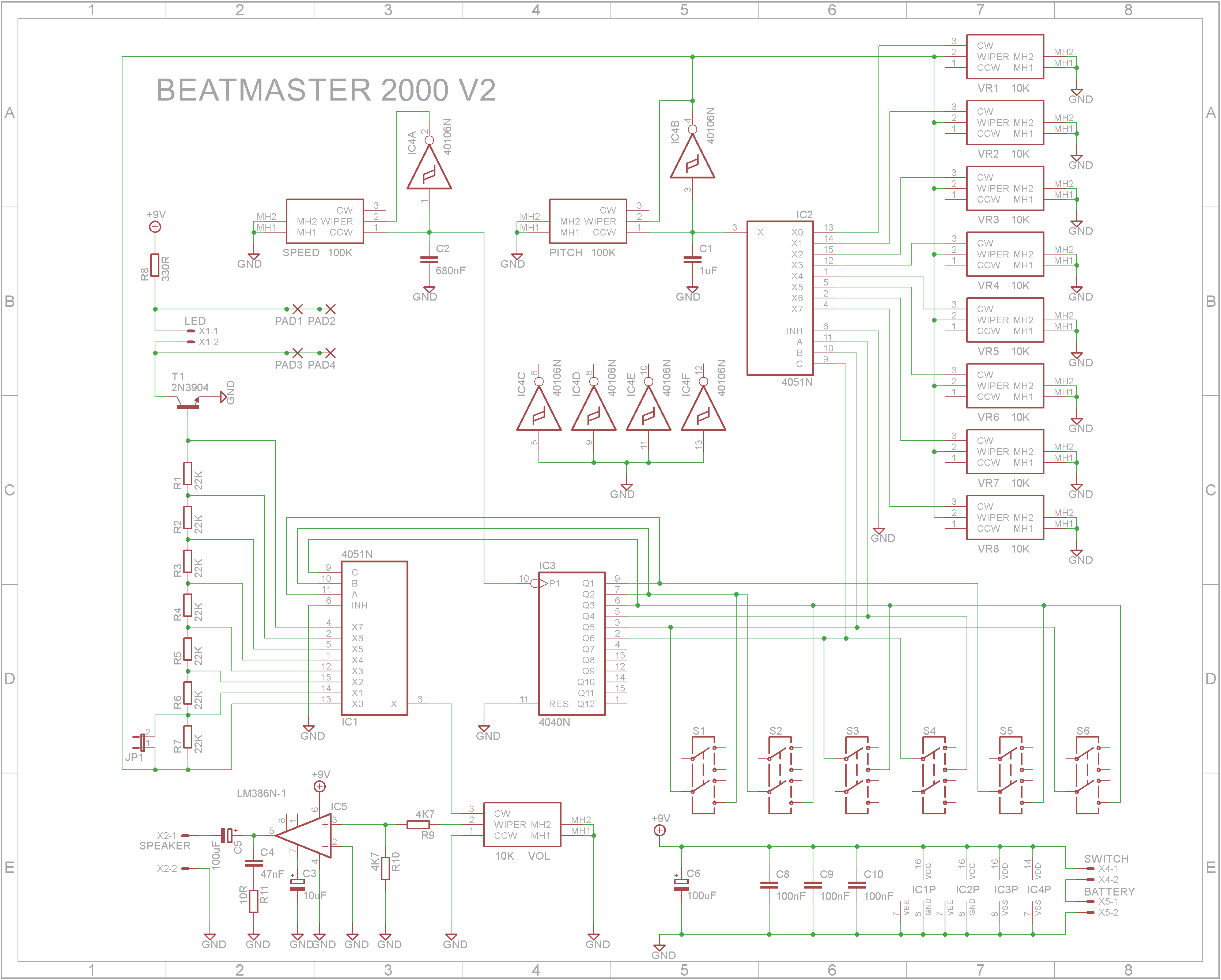
While browsing the Instructables website, I came across the Beatmaster 2000 by lonesoulsurfer. The sounds that it produces are quite interesting and varied. It does remind you of the sounds from the early games of the 80's.
While lonesoulsurfer provides excellent and detailed instructions on how to built the unit, I wanted to make my own PCB and have the case fully 3D printed. So this is my variant of the Beatmaster 2000.
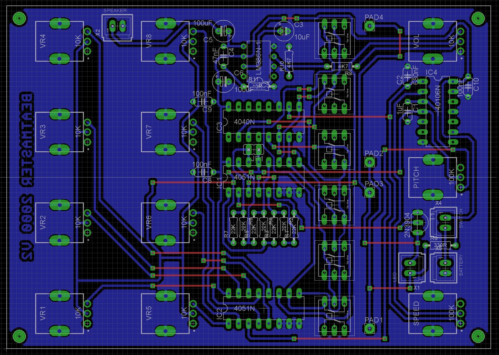
VideoPCBAs I was going to use the Toner method to make my own PCB, I redesigned the board to be single-sided. The component layout is basically the same.
The case ended up being the hardest part of the build. Because the 11 potentiometers and 6 switches are mounted on the PCB, it is easier if the PCB is fixed to the front panel. This means having the PCB mounts on the back of the front panel. I have found that when 3D printing text, it is more successful if the text is not on the build plate. This means the text will end up being the last few layers printed.
So as not to require supports because of the PCB mounts, I printed the top in two sections. The bottom part was printed with a 0.2mm layer height. The plan was to print the top part with 3 layers of yellow and 2 of black (the text layers) and glue it to the bottom part. However this failed mainly due to where the glue was. The yellow appeared darker in areas where glue was present. This made the whole front look rather patchy and ugly. My final attempt was to print the first layer in black, the next two layers in yellow and the final two layers in black. (All layers being 0.2mm). I then stuck it to the bottom part using double-sided tape.
(HINT: make sure your build-plate as cooled right down before removing the print otherwise you may warp the front getting it off the build plate).
The knobs are printed using a 0.2mm layer height. Switch to a contrasting color at the start of layer 56. I used white as my contrasting color to match the button tops.
The bottom was designed for a 75mm diameter speaker I had lying around. The bottom of the case requires three 4mm M3 brass threaded insert nuts to be heat pressed into the speaker mounts. The speaker clips screw into these using 6mm M3 screws.
The parts list is attached. Where possible, I kept the same layout as the original. The connectors for speaker and power are soldered to the underside of the PCB. I didn't add a separate connector for the power switch and instead added a link across the holes where the connector would of gone.
Add the speaker, 9V battery, DC power socket, audio jack and rocker switch to the bottom of the case and wire up.
Add the top and admire your finished build.
This was a fun build so thank you lonesoulsurfer for sharing your project. 👍👍👍


Comments
Please log in or sign up to comment.