


Hardware components | ||||||
| × | 1 | ||||
Hand tools and fabrication machines | ||||||
 |
| |||||
 |
| |||||
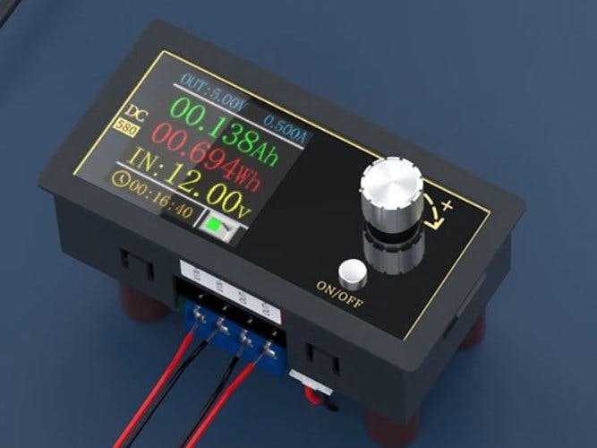
Recently I purchased a DC-580 Buck-Boost Convertor with PC connectivity from AliExpress for around AUD $25. This module takes an input voltage of 8V to 32V and outputs a voltage of 1.8V to 32V. It can output up to 5A as long as the wattage (voltage x current) stays under 80W. Like any good power supply, you can set the maximum current the circuit you are powering can draw.
Wiring the DC-580 module can't really be any simpler. I connected it to a power brick from a old discarded laptop. It outputs 19V at 4.74A. By adding a 3D printed case, it became a very useful desktop power supply.
Using the DC-580 Buck-Boost ConvertorThe DC-580 comes with a product manual but as far as explaining how to use the module, it's not very useful. Other than the on/off button, all functions are done through the rotary encoder.
On power-on, the Output setup screen is displayed. The rotary knob will switch between the following screens:
The OUTPUT SETUP screen allows you to set the output voltage and maximum current.
To set the output voltage and current:
- Hold down the Rotary Encoder button until the Voltage value turns white.
- Push the Rotary Encoder button to select the digit you want to change
- Turn the Rotary Encoder to adjust the output voltage.
- Once the voltage is set, hold down the Rotary Encoder button until the Current value turns white.
- Push the Rotary Encoder button to select the digit you want to change
- Rotate the Rotary Encoder to set the maximum current.
- Once the current is set, hold down the Rotary Encoder button until the the current turns blue again. You are now back to the screen selection mode.
To switch on/off the output voltage:
- Press the ON/OFF switch to switch on/off the output. The little switch icon will turn green when power is active at the output socket.
Changing options in the System & Parameter Setup screens:
- Turn the rotary encoder knob to the screen that has the option you want to change.
- Press the Rotary Encoder button to enable the yellow cursor bar.
- Turn the rotary encoder knob to the move the cursor to the option you want to adjust.
- Hold down the Rotary Encoder button until a popup menu appears.
- Turn the rotary encoder knob to the new value.
- Hold down the Rotary Encoder button until a popup menu disappears.
- Press the Rotary Encoder button to turn off the yellow cursor bar. You are now back to the screen selection mode.
One of the options you can get with this module is a small USB type C board that allows you to connect to a PC.
I have attached the software that runs on the PC. Run the setup.exe file to install the software on your PC.
The Power Supply software allows you to setup and monitor the power supply. While it is easier to set/change the values using your PC keyboard rather than using the rotary encoder on the unit, I didn't find the software added much to the overall usefulness of the power supply.
TestingI tested the power supply using my 30W Constant Current Load that I made previously. You can't really expect super precision from such a low cost module. The output is certainly within the ball park of the projects that I tend to build.
Using a Dremel with a cutting wheel, open the black case that surrounds the power brick. Carefully remove the board from the case. My board was encased in a tin shield which I removed.
You will probably find that any shield is soldered to the PC board by one or more pins. Since you want to put the shield back after making the changes to the input and output, you need to be very careful not to damage these pins when removing the shield.
Once open, remove the AC power socket and add wires to the L, N and E connection points. Remove the old DC output cable and add new wires to the +19V and GND connection points. Once that is done, you can put back the shield.
Building the caseI designed a case to hold the power supply and DC-580 Buck-Boost Convertor. The STL files are included. Either take these to a 3D print shop or if you have your own printer, run them through your slicing software. I used a 0.2mm layer height and they need orientating in your slicing software.
The lugs that hold the shells together are a bit fragile. I glued on washers before I drilled the holes with a 2.5mm drill and created a thread with a 3mm tap. Drill out the holes that the screws go through with a 3mm drill.
The base contains a holder that is designed to fit the Laptop power supply. The power supply is hot glued into the holder. The rest of the components are mounted on the front and back panels.
The USB board is held in place with two M3 6mm screws. Drill out the mounts with a 2.5mm drill and create a thread with a 3mm tap.
This is a fantastic module and is a great way to put some of those power bricks that have been salvaged from old laptops to use. The PC connectivity is interesting but really doesn't seem to add much. The display is clear and easy to read. Overall it makes for a professional looking power supply.


Comments
Please log in or sign up to comment.