


Hardware components | ||||||
 |
| × | 1 | |||
 |
| × | 1 | |||
| × | 42 | ||||
 |
| × | 1 | |||
 |
| × | 2 | |||
 |
| × | 1 | |||
 |
| × | 1 | |||
| × | 42 | ||||
 |
| × | 1 | |||
Software apps and online services | ||||||
 |
| |||||
Hand tools and fabrication machines | ||||||
 |
| |||||
 |
| |||||
This novel clock was inspired by the Domino Wall Clock by Carbon Design Group. This 3D printed version makes a interesting desktop clock.
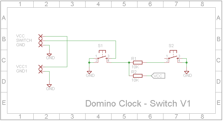
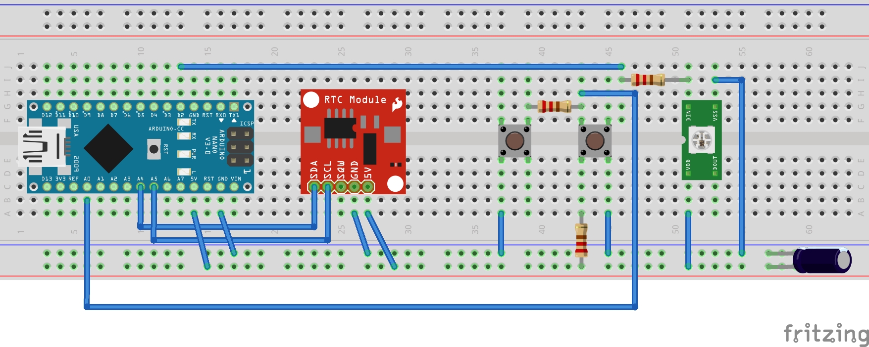
DemonstrationCircuit designEach domino has 14 RGB WS2812B LEDs. One domino contains two buttons to allow you to set the time. An Arduino Nano and DS3231 Real Time Clock are contained in the base of the clock. The clock is powered via the Arduino Nano's USB port.
The STL files have been included. Either take them to a 3D print shop and get them printed or if you have your own 3D printer, run them through your slicing software.
"Domino - Top.stl" - 3 off, 0.2mm Layer Height, All supports
"Domino - Cover.stl" - 3 off, 0.2mm Layer Height, All supports
"Domino - Back.stl" - 2 off, 0.2mm Layer Height, No supports
"Domino - Switch.stl" - 1 off, 0.2mm Layer Height, No supports
"Domino - Base.stl" - 1 off, Rotate 180 degrees, 0.2mm Layer Height, All supports
Assembly - Step 1Once you obtain the parts, you will need to modify the DS3231 RTC module. Remove the battery holder and any headers. Solder two wires from the SMD battery holder to the holes on the DS3231 module where the battery used to be. Make sure you wire the positive of the battery holder to the positive hole on the DS3231. Same applies with the negative wire.
Place 14 LEDs into one of the "Domino - Top.stl" that you 3D printed. Make sure the DIN and DOUT connections on the LEDs match the layout below. Connect the top and bottom rows using tinned copper wire. Using thin wire (I used Wire Wrap wire), wire up the middle LEDs to complete the chain.
If you have a tester like my WS2812B Tester, connect it to the 5V, DIN and GND and test the LEDs all work correctly.
Assembly - Step 3Turn the domino over and add the glass cabochons into the holes. Slide on the "Domino - Cover.stl" to hold the cabochons in place.
For the left domino, add connecting wires to VCC, DIN and GND.
For the middle domino, connecting wires to VCC, DIN, DOUT and GND.
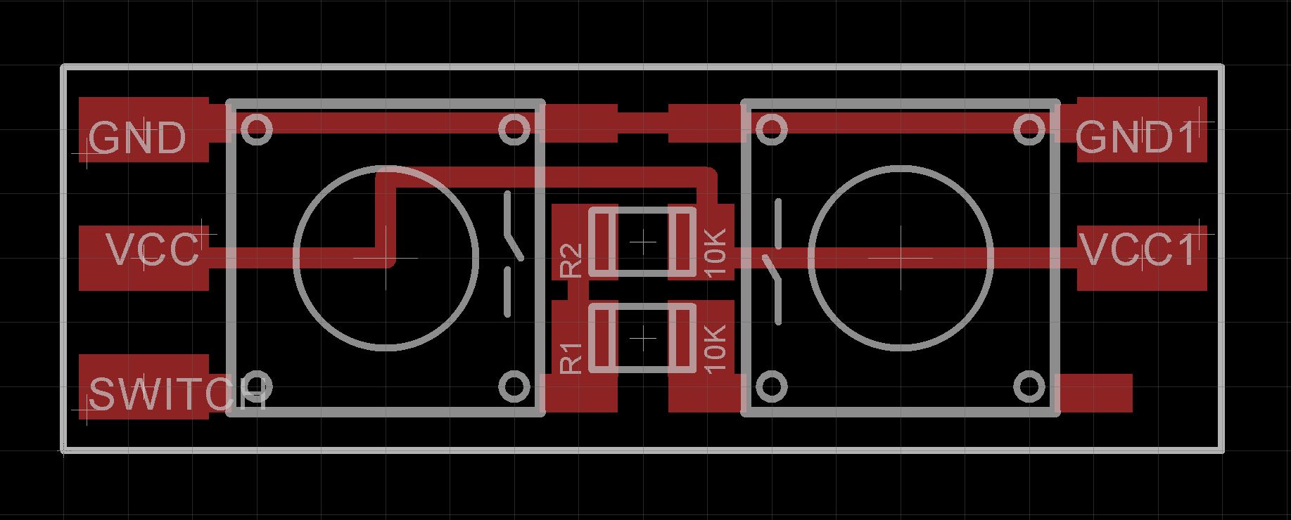
The switch unit for the right domino was soldered onto a home-made board. I have attached the Eagle files should you wish to get this board commercially made. I made mine using the Toner method. Although I didn't try this out, you maybe able to use a small piece of proto board to hold the two switches and two resistors. Board size is 0.9in x 0.3in
Connecting wires to VCC, DIN, DOUT, GND and SWITCHES.
Feed the connecting wires through their respective holes on the base and apply a bit of super glue to fix the dominos to the base.
Once the glue dries, starting with the left hand domino, connect its DIN to the middle domino's DOUT. Also connect the VCC and GND wires.
Connect the middle domino DIN wire to the right domino's DOUT. Also connect the VCC and GND wires.
Add some hot glue under the battery holder and push it into its slot. Add four wires to the SCL, SDA, VCC and GND holes on the RTC and hot glue it onto its mount.
On the DIN wire of the right domino, add a 330 ohm resistor as shown below. On the Arduino Nano, add the 470uF 10V capacitor across 5V and GND. I added it to the ICSP holes. (See picture).
Wire up the Arduino Nano.
- VCC wire to 5V pin
- GND wire to GND pin
- DIN wire to D2 pin
- SCL wire to A5 pin
- SDA wire to A4 pin
- SWITCHES wire to A0 pin
Hot glue the Arduino Nano onto its mount. Add a bit of hot glue to hold the 470uF capacitor in place.
Connect the USB cable from your PC to the Arduino Nano. Open up the Arduino IDE and upload the attached sketch.
There are two #defines near the start of the code that allow you to change how color is used. You can have monochrome (white dots), fixed color (as below) or animated colors.
Like my Roman Numeral Clock, this clock suffers the same problem. There is no representation of the number zero. When the time contains the digit 0, the corresponding domino is unlit. This tends to spoil the overall effect.


Comments
Please log in or sign up to comment.