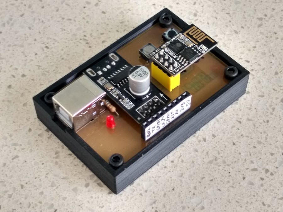
The ESP-01 is a cheap WiFi board based on the ESP-8266 microcomputer. I have used this board in a number of my projects and the biggest hassle has been to develop software for it. This is mainly due to switching between the programming and run-time environment.
In my Embedded NeoPixel LED Christmas Tree remake, the ESP-01 needs to be unplugged from the programmer and inserted in the tree to test.
Also you can't use the Ardunio IDE console while the ESP-01 is not on the programmer. So this ESP-01 development kit was made to eliminate these problems.
Disassembling the ESP-01 programmerThe first thing you notice about the ESP-01 programmer is the USB Type A plug. My preference is a USB Type B socket as they are very robust and take a lot of punishment. Secondly, I wanted to bring out the pins to a header so that I can access any pin using jumper leads.
Carefully prize off the yellow plastic case of the 8 pin header. Remove each pin one-by-one. Do not apply heat for too long otherwise you might damage the through hole plating. Now take off the USB Type A plug using a good solder sucker. Clean up all the holes with your solder sucker.
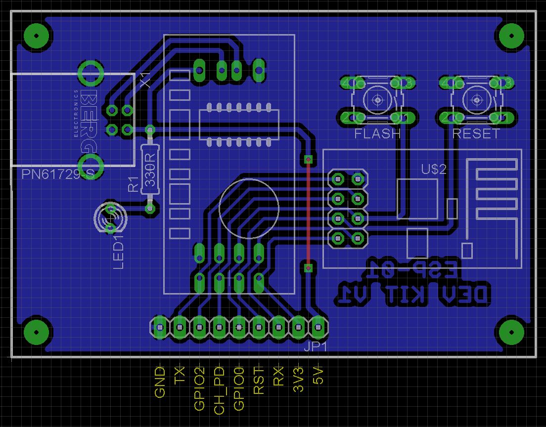
Solder on a 8x2 pin male header and a 4x1 male pin header. This will allow you to plug the ESP-01 programmer into the PCB. I reinserted the pins into the yellow 8 pin female header and used it again on the PCB.
Making the caseThe STL file is included so you can 3D print the case or get it made from a commercial 3D print shop. Use a 0.2mm layer height and a 20% infill. Supports are not required. Drill out the PCB mount holes with a 2.5mm drill and create a thread using a 3mm tap. Use M3 6mm screws to hold the board in place.
Making the PCBThe Eagle files have been included should you wish to have your board commercially made or do as I did and make them yourself. I used the Toner method. Add the rest of the components.
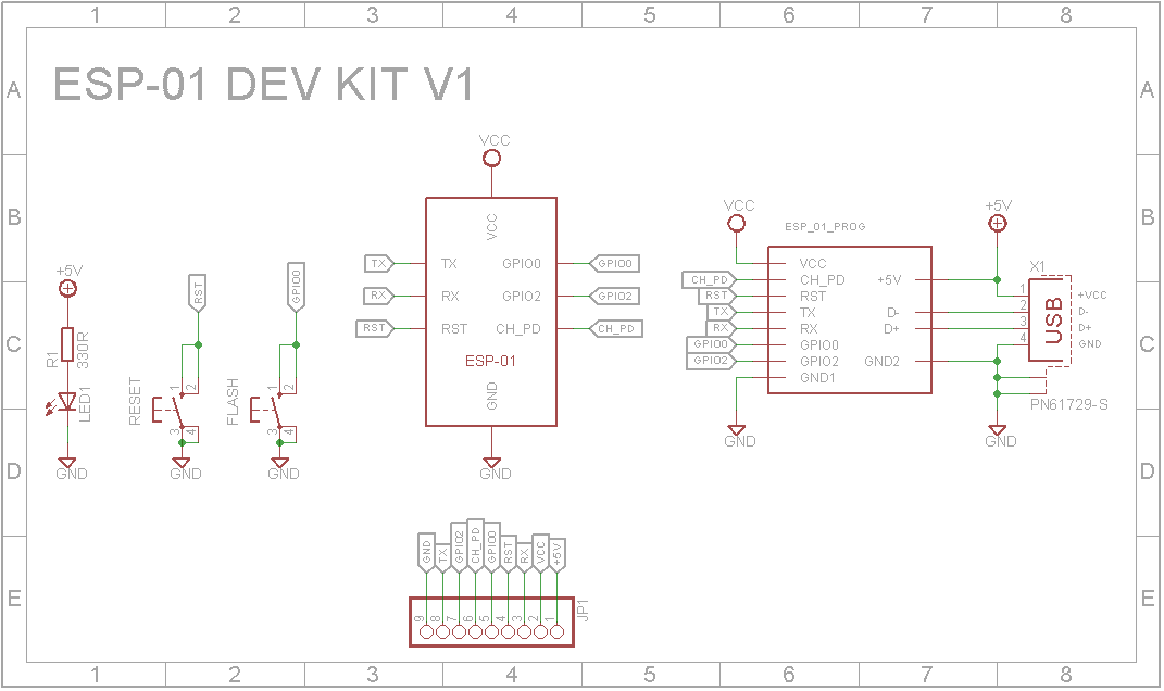
The programmer has two buttons. The Reset button by itself will reset the ESP-01 and start whatever program you have uploaded to it. Holding the Flash button while pressing the Reset button with start the ESP-01 in flash mode. This allows you to upload a sketch via the Arduino IDE.
If you haven't already done so, you need to install the drivers and board definitions. For a description on how to do this, see the following link:
Flash Program ESP-01 using USB Serial Adapter
To program your ESP-01 connect a USB cable to your PC. In the Arduino IDE, select the board to be "Generic ESP8266 Module" and the programmer to be "AVR ISP". Hold down the Flash button and press the Reset button. You should be good to go ahead and upload your sketch.
The GPIO0 pin is what determines whether the ESP-01 boots up in Flash mode or Run mode. If it is low during power-on or when the Reset button is pressed, the ESP-01 will enter Flash mode.
My first circuit I created for the Embedded NeoPixel LED Christmas Tree remake was as follows:
The GPIO0 pin drives a transistor that connects to a buzzer. Looking at it, the circuit as appears to the IO pin is basically a 1K resistor in series with a forward bias diode to ground. This meant the ESP-01 always powered on in flash mode. I don't know how many hours I wasted trying to figure out why it wasn't working.


Comments
Please log in or sign up to comment.