


Hardware components | ||||||
| × | 1 | ||||
Hand tools and fabrication machines | ||||||
 |
| |||||
 |
| |||||
Living in a small unit can be challenging when it comes to space. My desk and workbench are one in the same. As I use my desktop computer for most of my computing needs, it needs to always be available and in a prominent position. When it comes to my hobby, my soldering station, reflow station, power supply, oscilloscope and function generator also need to be close at hand. This means space is always at a premium.
Many times I have needed multiple power sources. Maybe it is to power some piece of extra equipment or to power the project I am working on or maybe I need a dual positive & negative supply for a op-amp project. While the 30V 5A adjustable power supply built into my solder/rework station does most jobs, it doesn't solve some of the issues mentioned above.
My first version of a bench-top power supply was basically four independent fixed 12V power supplies with built-in current limiting.
While version 1 served me well, there were times that I wished I had a 5V supply or that it could deliver more current.
So version 2 was born. Because the power supply had to basically fit the gap between the monitor and the soldering/reflow station, it could not exceed 40mm in height. This makes it tough to layout the front panel with everything needed for multiple power supplies.
Variable power supplyThe variable power supply comes from a 19V 3.5A power brick that I had lying around. I think it was for a lap top computer. I cut away the black case with a Dremel to obtain the PCB. Next I got one of those XL4015 modules with voltage and current meters from eBay.
The four brass spacers are the actual connections between the XL4015 board and the voltage and current meters. I removed the I-ADJ 10K trim pot, V-ADJ 10K trim pot, DC-IN connector and DC-OUT connector from the XL4015 board. I also took off the white JST sockets from the display board. The PCB board is designed to allow the mounting the XL4015 board with wires running from the exposed pads left by the removed parts to the PCB.
The voltage and current multi-turn trim pots are replaced with a 10K pot (coarse) in series with a 1K pot (fine). Multi-turn pots are not used because there isn't enough room to fit them on the front panel. Looking at the picture below, the green wire goes to the 1K pot and the brown wire links the 10K and 1K pots together.
You can source the green potentiometers on eBay or AliExpress. You may find the 1K linear pots hard to source. I did find one vendor on AliExpress who had them.
Fixed power suppliesI kept two of the 12V power supplies from the version 1 build. The 12V is outputted by a 240VAC to 12V DC 450mA supply module.
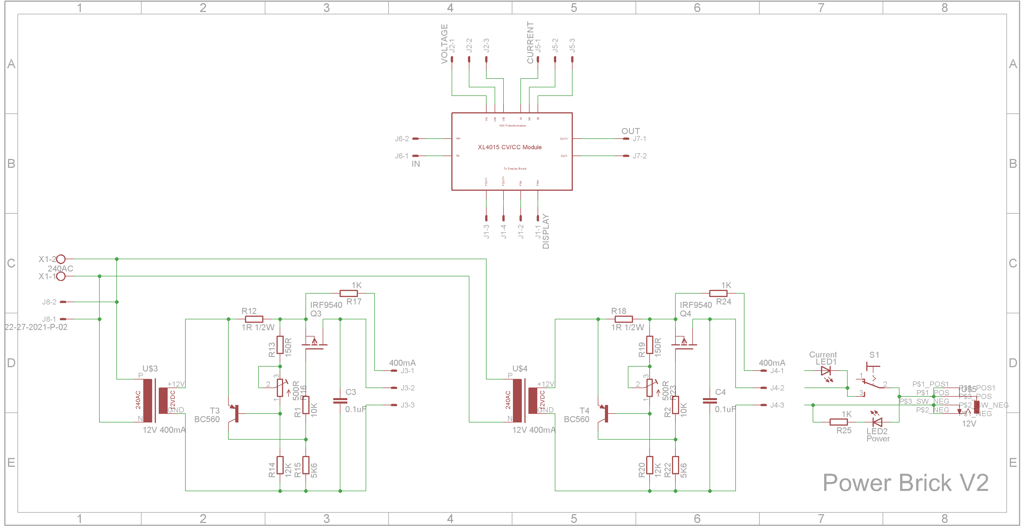
There is a current sensing circuit that will trigger when current exceeds a predefined amount. This is determined by the trim pot. I set mine to trigger at 350mA. When the current system trips, the red LED will illuminate. The green LED shows that the output socket is live. The schematic shows what parts are on the PCB and what parts are wired on the front panel.
The push button switches used are "PUSH BUTTON SWITCH LATCHING ON/OFF DPDT 0.5A 50VDC 8x8mm" from Tada Electronics. They also have the button caps for these switches in a range of colors.
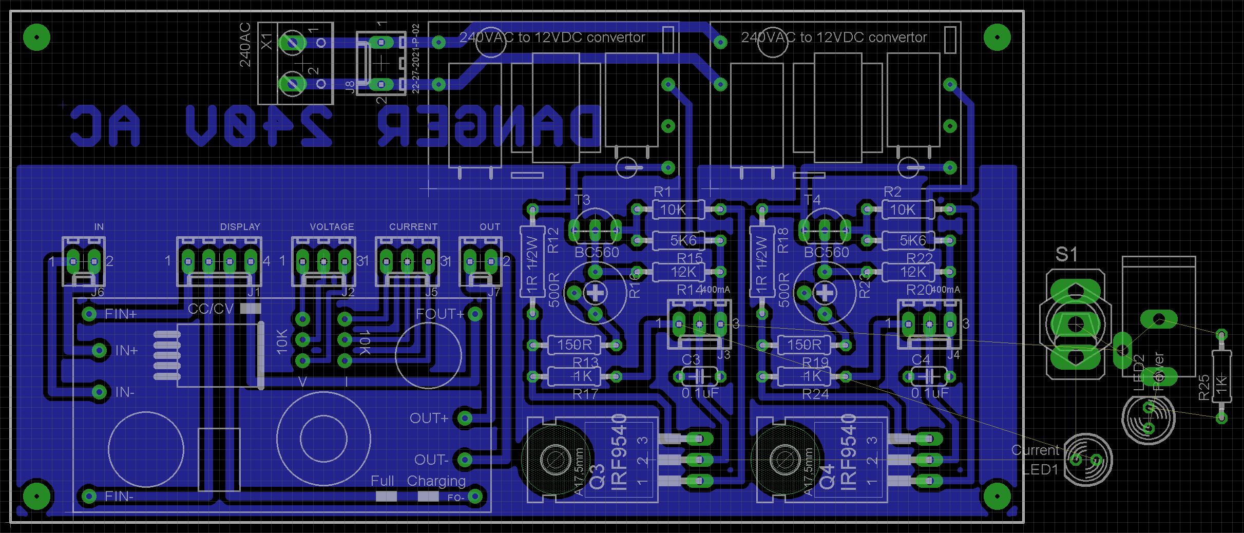
Building the power supplyI designed the case to match the power supply board that I extracted from the 19V 3.5A power brick. If you plan to build this, I wish you luck on trying to find one the exactly same size.
The STL files are included. Either take these to a 3D print shop or if you have your own printer, run them through your slicing software. I used a 0.2mm layer height and they need orientating in your slicing software.
On the base, drill out the four PCB mounting holes with a 2.5mm drill and create a thread with a 3mm tap.
The lugs that hold the shells together are a bit fragile. I glued on washers before I drilled the holes with a 2.5mm drill and created a thread with a 3mm tap. Drill out the holes that the screws go through with a 3mm drill.
Assembly of the PCB should be straight forward. The 240VAC socket on the back of the unit and associated power lead came from an old VCR. The rest of the components came from eBay or AliExpress.
The variable power supply works better than expected. The only issue I have with it is the 1K pots are still too coarse when adjusting the voltage or current. The 12V fixed supplies work OK but I have run into issues of them not providing enough current.
UpdateI replaced the two 12V supplies with two 12V 2A power bricks. The PCB is cut in half to make room for each of the power bricks' internal module.

Comments
Please log in or sign up to comment.