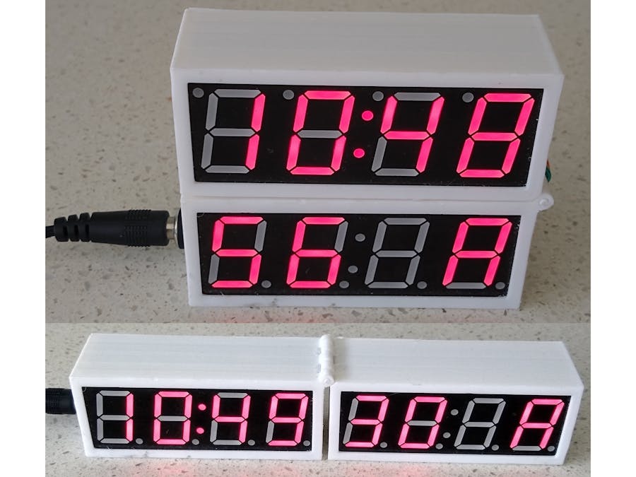
Recently I build a Cube clock that showed the time in the same orientation no matter what orientation the clock itself was in. This was inspired by the Lexon Flip Travel Reversible LCD Alarm Clock. One of the other thoughts that I had at the time was a folding clock.
DesignThis clock was designed based on components that I already had on hand; mainly the two 0.8in 4-Digit 7-Segment clock displays. Since the clock is in two parts, it made more sense to use two 4-Digit, 7-Segment display drivers (TM1650) rather than a single MAX7219 8-Digit 7-Segment display driver.
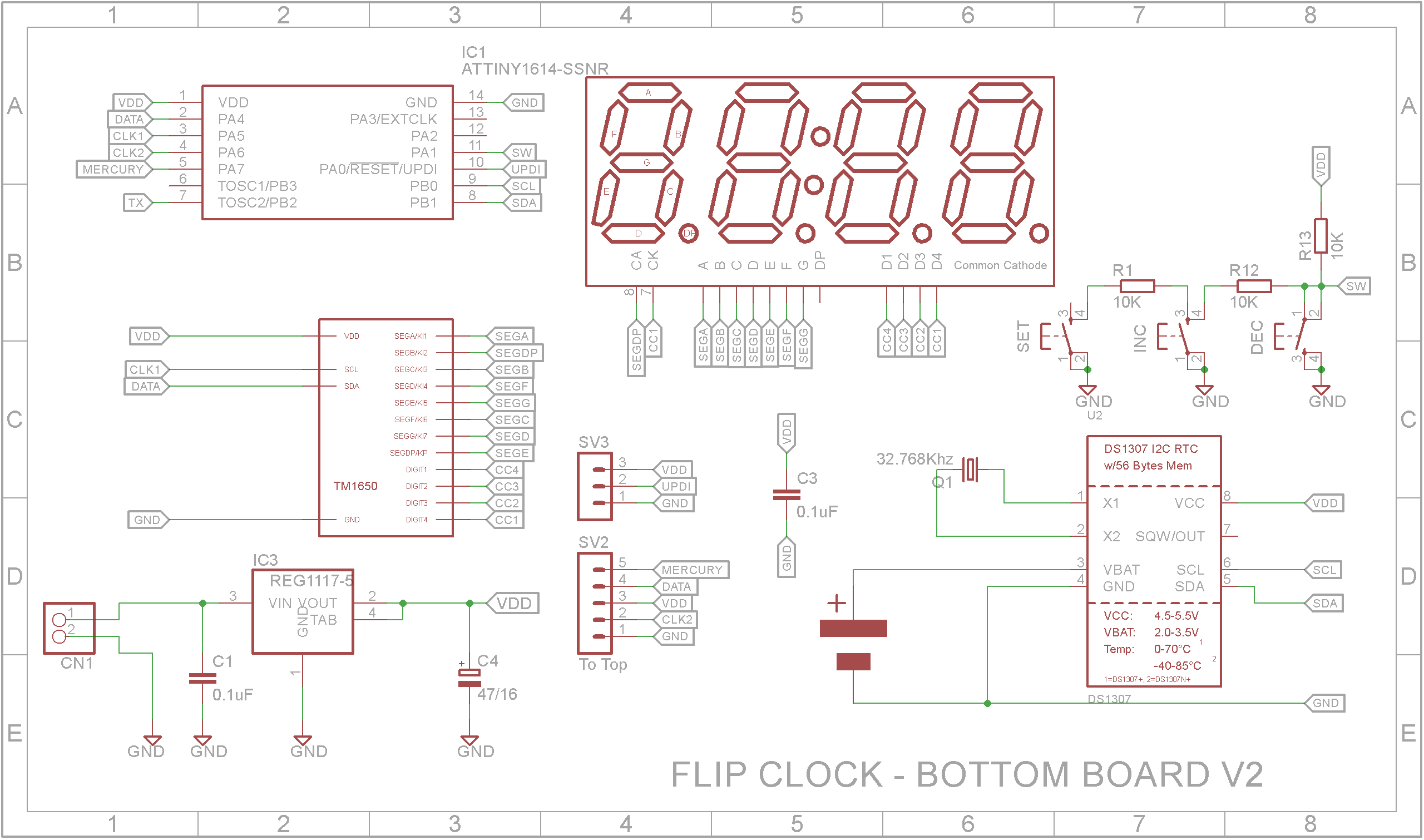
Most of the electronics are in the bottom or left hand section. Time is controlled by a Real Time Clock chip (DS1307) and it has its own battery so as to not lose any time when the main power supply is disconnected.
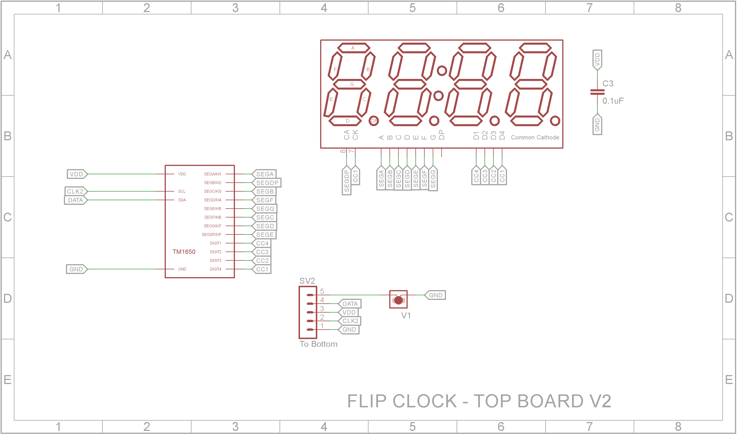
The top or right hand section contains a mercury switch that determines whether the top section is folded back or is opened out.
The clock is configured using three buttons. These are SET, UP and DOWN. The SET button flashes the HOURS, MINUTES and SECONDS values in order. While the value is flashing, the UP and DOWN buttons will either increase or decrease the value respectively. Any changes are written back to the RTC.
You can set the time when the clock is folded back on itself or is fully open.
3D printingThe STL files are included. Either take these to a 3D print shop or if you have your own printer, run them through your slicing software. I used a 0.2mm layer height.
The hinge pin is a piece of 1.75mm filament. I found the hinge started out quite tight but loosen up after opening and closing it a number of times.
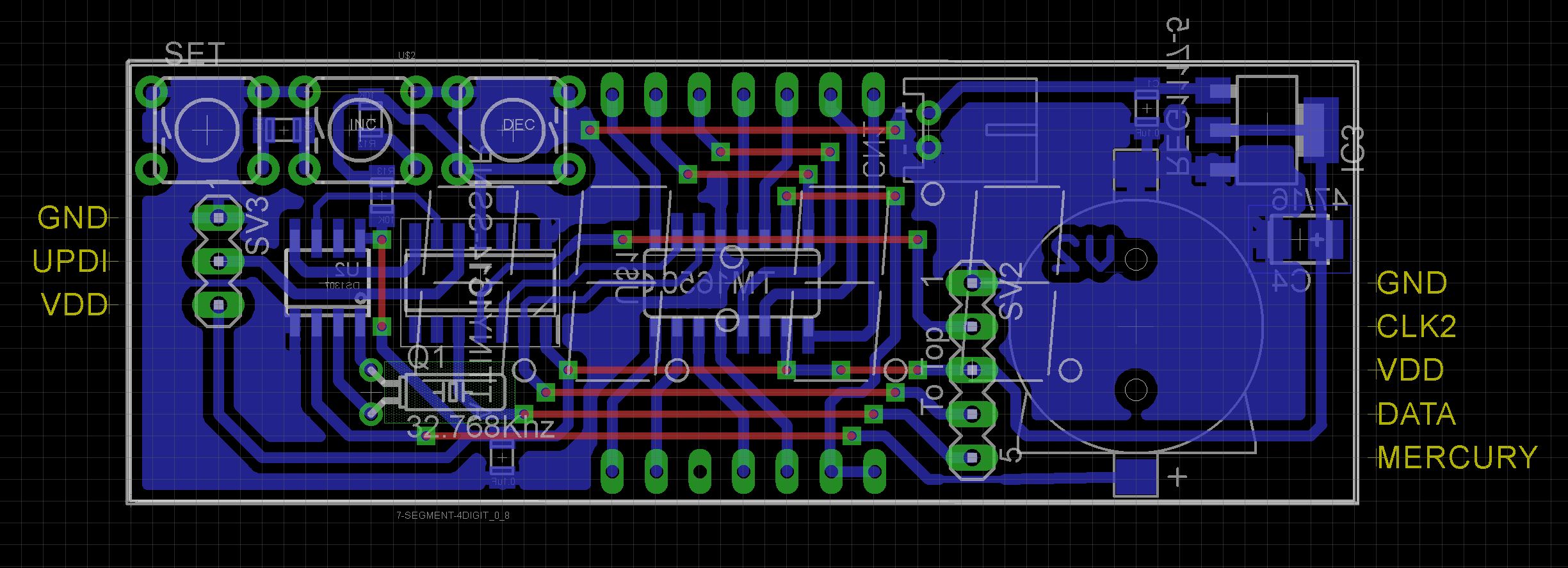
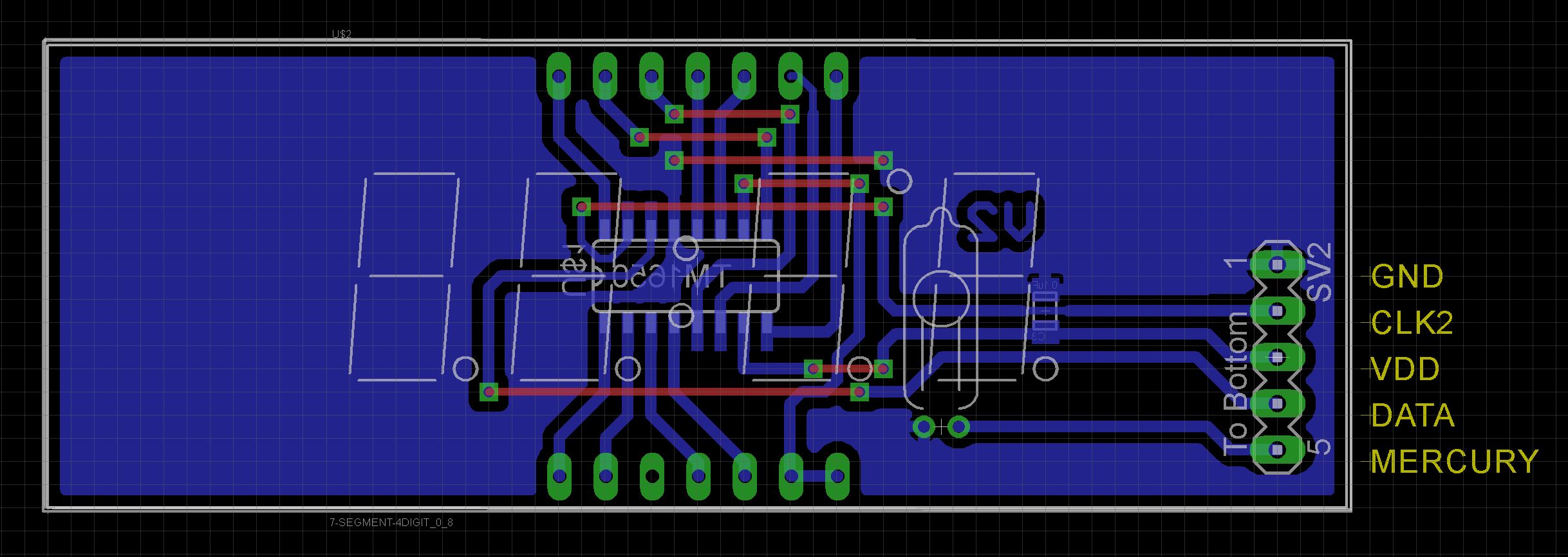
To minimize the space required, the board has been designed to use Surface Mount Devices (SMD) where possible. Also the boards are designed to be the same size as the 0.8in 4-Digit 7-Segment displays.
When designing the boards, I didn't map the segment pins to their corresponding display pin but rather kept the layout as simple as possible and adjusted for it in the software.
The Eagle files have been included should you wish to have the board commercially made or you can do as I did and make it yourself. I used the Toner method.
Assembly - Step 1Start by adding the SMD components. I find it easier to use solder paste rather than use solder from a reel when soldering SMD components. Leave the battery holder off for the time being.
Add the links if you are using a single sided board
Add the UPDI programming pin header, the link pin header and the JST power socket to the bottom board.
Add the link pin header to the top board.
Note: I usually dab a bit of paint on my connectors to show the correct orientation for any connections that might be made to them.
Assembly - Step 3Add the mercury switch and display to the top board. (Make sure you don't solder the display in upside down!)
Now that the pin headers are in place, you can add the battery holder.
Before adding the 32.768Khz watch crystal for the RTC, wrap it in some Kapton tape before soldering it on the copper side of the board. This will ensure that it doesn't short out any tracks underneath.
Glue on the button tops onto the 17mm 6x6mm tactile switches. Take care that the glue doesn't run down the shaft and into the switch. Solder on the switches starting with the middle one first.
Add the display to the bottom board. (Make sure you don't solder the display in upside down!)
Place the boards into the 3D printed case. Add the DC power socket and wire it to the JST plug. Next feed though a 5 way ribbon link cable through the slots just under the hinge and plug it into the boards.
After programming, use hot glue to hold the boards in the case.
The ATtiny1614 is part of the new breed of ATtiny microprocessors. Unlike the earlier series such as the ATtiny85, the new breed use the RESET pin to program the CPU. To program it you need a UPDI programmer. I made one using a Arduino Nano. You can find complete build instructions at Create Your Own UPDI Programmer. It also contains the instructions for adding the megaTinyCore boards to your IDE.
Connect the UPDI programmer
Once the board has been installed in the IDE, select it from the Tools menu.
Select board, chip (ATtiny1614), clock speed (20MHz) and the COM port that the Arduino Nano is connected to.
The Programmer needs to be set to jtag2updi (megaTinyCore).
Open the sketch and upload it to the ATtiny1614.
ConclusionI main issue I have with this clock is the cable that joins the two sections. It really needs to be one of those bendy printed cables that you might find on a CD-ROM drive. The problem is getting one the right length and having the correct sockets so that it can be plugged in.
Overall an interesting project that presented some challenges when designing the code.






Comments