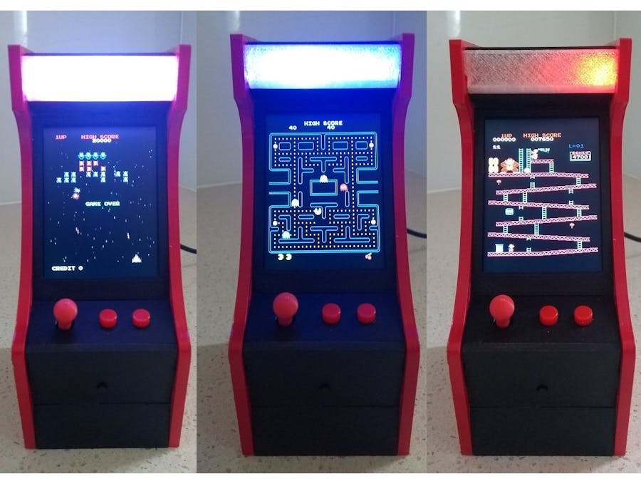
Recently while on the GitHub website, I came across a miniature playable laser cut arcade emulator called Galagino - ESP32 Arcade Emulator by Till Harbaum. It incorporated ESP32 variants of three of the greatest arcade games of the early 80s. These are Pacman, Galaga and Donkey Kong. I was so impressed by the quality of emulation using a ESP32 microprocessor that I had to make one. Unfortunately I don't have access to a laser cutter so instead I set about redesigning the case for a 3D printer.
Most of the printing for the case was done using white PLA at a 0.2mm layer height.
"Case - Marquee.stl" should be done using transparent PLA.
"Case - Knob V2.stl" should use a 0.1mm layer height and a raft. I also printed it using red PLA.
The control panel and coin button holder were redesigned to remove the screw holes giving the final unit a "clean" look. The sides have been widen so to cover the tab holes on their outsides. This also adds to the "clean" finish of the case.
Most pieces fit to each other via the use of tabs similar to the laser cut version. You will probably need to file the tabs so they fit cleanly into their respective tab slots. Ensure everything fits before painting and adding the components.
The case is held together with 4 x M2 nuts pressed into the bottom and top pieces with 4 x 12mm M2 screws connecting the sides.
The Eagle files have been included should you wish to have the boards commercially made or you can do as I did and make them yourself. I used the Toner method. Gerber files are also included.
One of the changes that was made was to replace the four tactile switches that made up the joystick in the original with a more reliable 5-way switch. This along with the other two buttons are mounted to a printed circuit board
The control PCB is fixed to the underside of the control panel using 4mm M2 screws. Use standard button tops for the two switches and 3D print "Case - Knob V2.stl" for the 5 way switch knob.
The CPU board holds the ESP32 development kit and the PAM8302 3W Amplifier Module. It also contains pin headers to connect to the screen, control board, LED strip etc.
Start by adding links if your board is single-sided.
Add the pin headers to the copper side.
On single sided boards, this is how I add my pin headers. Start by soldering the pin header with the long side of the pin facing down. Carefully pry off the plastic and turn it upside down and push it back down onto the pins as low as it will go.
Add female headers on the component side of the PCB and plug in the ESP32 development kit.
Solder on the PAM8302 3W Amplifier Module and trim any excess off the pins. Screw the PCB onto "Case - Base V2.stl" using 4 x 6mm M2 screws.
Using super glue, glue "Case - Display Support V2.stl" to "Case - Right V2.stl".
Connect wiring to a strip of 7 WS2812B LEDs and fix to "Case - LED Holder.stl". Plug the LED assembly into "Case - Top V2.stl".
Screw in "Case - Top V2.stl" and "Case - Base V2.stl" using 12mm M2 screws.
Plug in "Case - Display Bezel.stl", "Case - Display Top.stl" and "Case - Marquee.stl".
Before you slide in the TFT display, carefully bend the pins so that the female Dupont plug will clear the back of the case. Also do this on the control panel pin header.
I used a 15cm Dupont cable to connect the display and a 10cm Dupont cable to connect the control board. You can purchase these pre-made from sites like AliExpress, eBay etc. I removed the single pin shrouds and replaced them with 9 pin shrouds and 7 pin shrouds respectively. (You can cut them from 10 pin shrouds if you can't get the exact sizes).
Plug in and connect control panel ("Case - Control V2.stl"), coin slot ("Case - Coin V2.stl") and "Case - Front.stl".
Screw in a 30mm x 70mm rectangular speaker to "Case - Back V2" using M2 washers and screws. Wire the speaker and connect to the PCB. Plug the back panel into the case.
Finally add the left side ("Case - Left V2.stl") and screw in place with 2 x 12mm M2 screws.
SoftwareUnzip the attached software into your project folder and upload it to the ESP32 development kit (Node32s) via the Arduino IDE.
ConclusionA great and enjoyable build. Many thanks to Till Harbaum for publishing his project. 👍👍👍


Comments