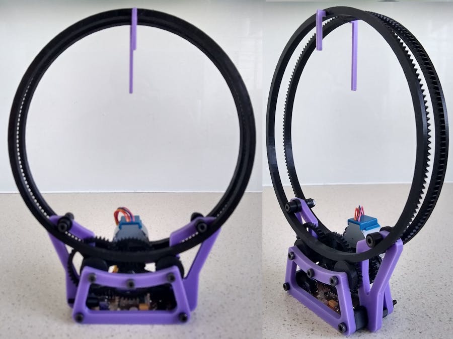
This is my build and changes to Ekaggrat's Holo Clock published on Thingiverse.
The changes that I made were:
- Use of a cheap 28BYJ-48 stepper motor
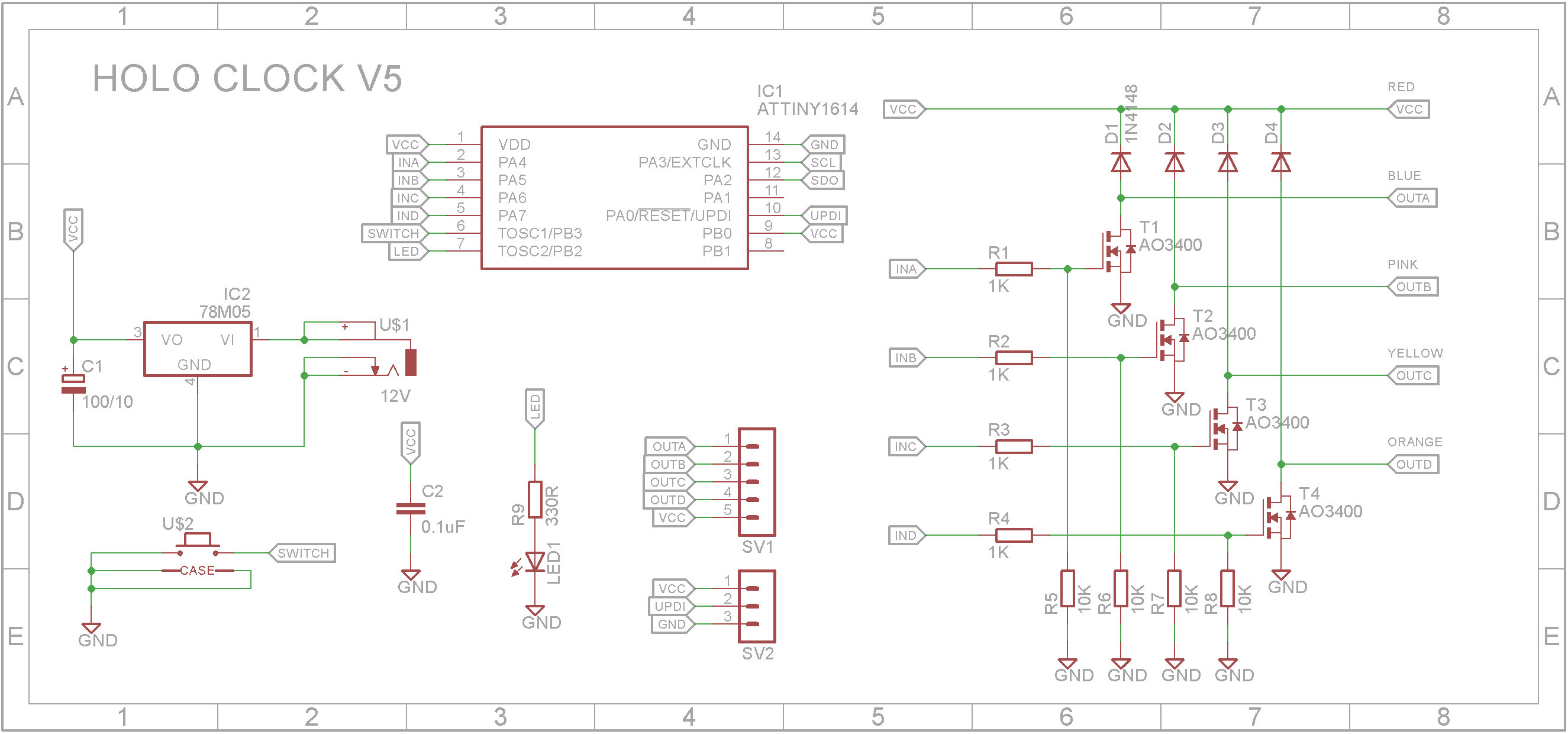
- New electronics based around a ATtiny1614 microprocessor
- New software
This build uses a 28BYJ-48 stepper motor so "frame_1__n.stl" and "motor_gear.stl" are replaced with "Motor Plate V1.stl" and "Motor_Gear_V1.stl" respectively.
Also "Rollers.stl" and "Spacers.stl" replace "p1.stl" and "SPACERS.stl" respectively.
Also "Button.stl" replaces "botton.stl".
As the gears need to rotate freely, I inserted 4mm brass tubes into each of the gears ("big_gear_1" to "big_gear_3"). You can buy these brass tubes from most hobby shops.
The circuit is built around a ATtiny1614 microprocessor. As the stepper motor is unipolar, it is driven by four N-Channel MOSFETs. A 5V regulator provides power from a 7V-12V power brick.
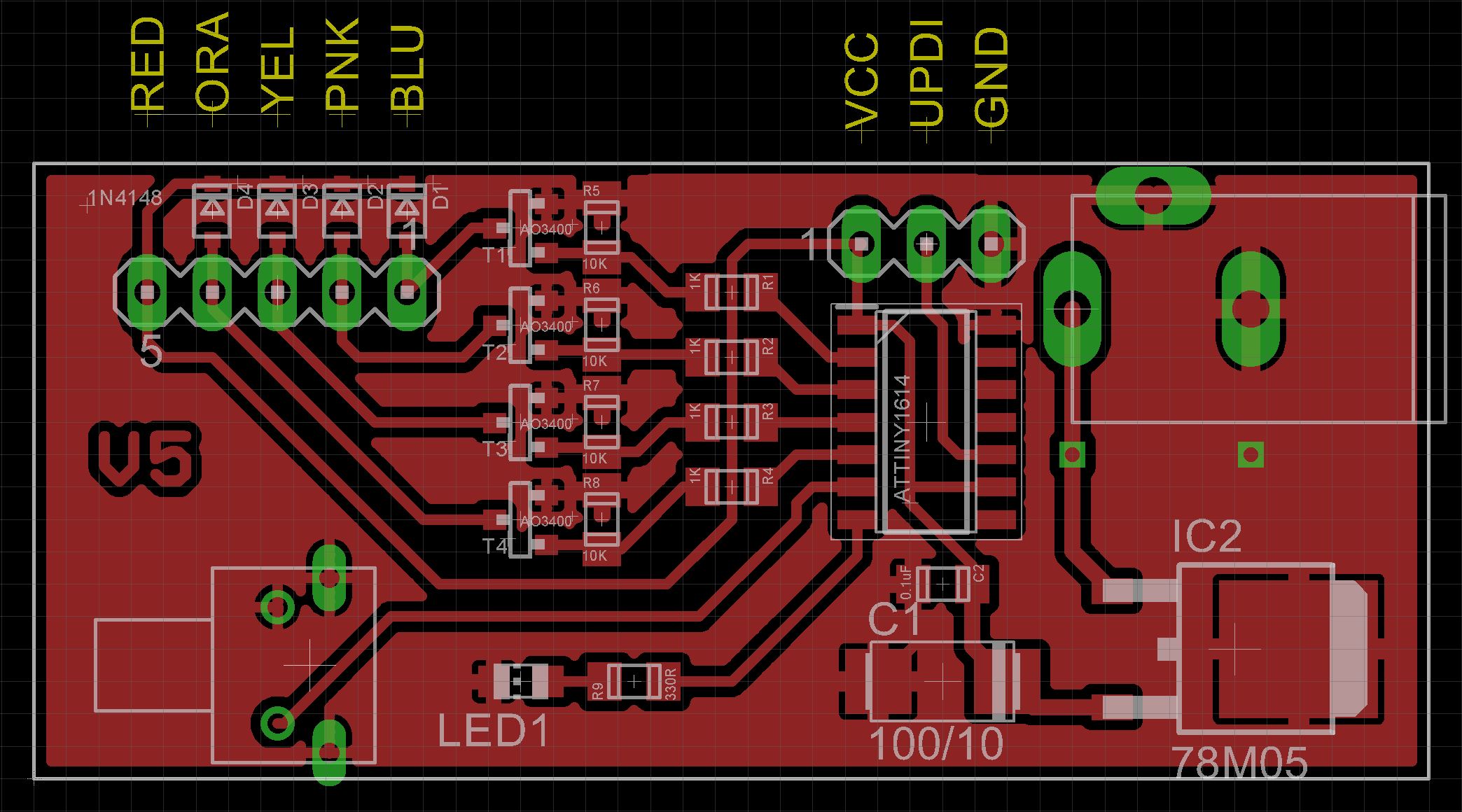
All the components are surface mounted. I have included the Eagle files in case you want to get the board commercially made or do as I did and make it yourself. I used the Toner method.
I won't go into assembling the clock here as Ekaggrat's instructions are attached. Instead I will cover the PCB assembly and any special changes I had to make to the original design.
Start by adding SMD components.
Add the 3 pin header for the UPDI programmer and the 5 pin header for the stepper motor connection.
Next add the tactile switch.
Add the DC power socket. If your board is single-sided, super glue the socket to the copper side and flatten the pins on the component side of the PCB. Solder two wires from the socket pins to the holes provided (see picture).
The DC panel socket gets in the way of one of the gears so you need to file down the inside back corner (see picture).
Insert "Button.stl" into the base ("base.stl") and glue the PCB to the base using hot glue.
Assemble the clock base using Ekaggrat's instructions that are attached.
One of the issues I came across is the 25mm bolts used to hold the rollers that will guide the two big rings stick out too far. When the rings are installed, the end of the bolts hit the hands of the clock. To remedy this, I designed new rollers and used 22mm bolts. The roller allows the hex end to be sunk into the roller and the other end of the bolt not to stick out past the nut.
Add the rings to the base.
Finally glue on the clock hands.
The ATtiny1614 is part of the new breed of ATtiny microprocessors. Unlike the earlier series such as the ATtiny85, the new breed use the RESET pin to program the CPU. To program it you need a UPDI programmer. I made one using a Arduino Nano. You can find complete build instructions at Create Your Own UPDI Programmer. it also contains the instructions for adding the megaTinyCore boards to your IDE.
Connect the UPDI programmer
Once the board has been installed in the IDE, select it from the Tools menu.
Select board, chip (ATtiny1614), clock speed (20MHz) and the COM port that the Arduino Nano is connected to.
The Programmer needs to be set to jtag2updi (megaTinyCore).
Open the sketch and upload it to the ATtiny1614.
ConclusionAs a talking piece, it succeeds 😃. As a time piece, it won't win any awards 🙁. Still it was an interesting and challenging build and I have to admit, it does look pretty cool 😎.


Comments
Please log in or sign up to comment.