


Recently I was looking to speed up the code that was used in my ATtiny1614 Function Generator. Simply put, the oscillator populates a 256 byte table with various amplitude values for a single cycle of the selected waveform and repeatedly sends these values to the DAC (Digital-to-Analog Convertor) built into the ATtiny1614 microprocessor. The maximum frequency that the outputted before it starts to degrade is based on the speed of the microprocessor and how many CPU cycles are required to obtain the next value and output it to the DAC.
In C, the "loop" to output these points is as follows:
while (!rotarySwitchPressed)
{
    phase += phaseInc;
    redPhase = phase >> 24;
    DAC0.DATA = waveform[redPhase];
}
This takes 57 CPU cycles to perform one iteration of the loop. With a 20MHz clock, this means it takes 1/20,000,000 * 57 = 2.85uS to output one point from the waveform table. As the waveform table contains 256 values for a complete cycle, the fastest this code can output a complete cycle is 1 / (2.85uS * 256) or 1,370 Hz. So to output higher frequencies above 1,370 Hz, it must start to skip points in the table. This means the output degrades, the higher the frequency becomes.
There isn't a lot more you can do in the C language to speed up the "loop" code. When you compile your C code, the compiler (AVR-GCC) converts your code into a language the microprocessor understands (machine code). The human readable form of this code is called assembly language. While the C language remains the same across different CPUs such as Intel or AVR or PIC processors, their assembly language is very different. I will be using the 8-bit AVR Instruction Set in this tutorial. (PDF attached). This is the machine code supported by the ATtiny1614, ATmega328, etc.
Although the C compiler generates assembly language behind the scenes, it will never be as efficient as coding directly in assembly language. To rewrite the loop in assembly language, you need to understand some basic internals of the AVR microprocessor.
RegistersBack when microprocessors first came on the market, the CPU, static RAM, non-volatile memory (usually ROM back then), IO Ports, Clock, etc were separate physical ICs. When the SOC (System On a Chip) came into existence, these were all incorporated onto a single chip. However even though they are all on the same die, memory inside the CPU part is accessed much faster than static RAM or non-volatile memory (usually Flash memory these days). This internal CPU memory is called a register set and is an integral part of all CPU operations.
The 8-Bit AVR processor has 32 8-bit general purpose registers labelled r0 to r31. Some of these are reserved for special functions, others are available for you to use as you wish. Most assembly language instructions operate on one or more of these registers. In general to manipulate some variable in static memory, you need to load it into a register, perform whatever function you want to do on that register and then store it back into static memory.
Addressing modesAs mention above, nearly all instructions operate on registers. There are various ways to initialize or save a register. I'm going to just cover the most common modes.
Immediate
ldi r, kImmediate addressing is initializing a register with a constant 8-bit value. In the assembly code, ldi is the mnemonic for LOAD IMMEDIATE, r represents a register (r0 to r31) and k represents a constant (0 to 255).
Direct
lds r, addressDirect addressing is initializing a register from a memory location in static memory. In the assembly code, lds is the mnemonic for LOAD FROM DATA SPACE, r represents a register (r0 to r31) and address is the memory location to load the value from.
The corresponding instruction to save a register is:
sts address, rld r, X
ld r, Y
ld r, ZRegisters R26 and R27 are also known as the X pointer, similarly R28 and R29 are also known as the Y pointer and R30 and R31 are also known as the Z pointer. A pointer can contain the address of a location in static memory. So rather than in the case of direct addressing where the instruction specifies the address of the value, indirect addressing uses one of the pointers to specify the address to get the value from.
In the assembly code, ld is the mnemonic for LOAD, r represents a register (r0 to r31) and X, Y or Z is the pointer that contains the address to load the value from.
The corresponding save instructions are:
st X, r
st Y, r
st Z, rWhen working in C, you have various data types at your disposal such as byte, int, long, float, etc. In 8-bit AVR assembly code, mostly everything is 8-bits. To manipulate a 32 bit number (equivalent to an unsigned long in C), you will need 4 registers to store it. 8-bit AVR processors are what is known as little-endian. What this means is a number greater than 8-bits is always stored with is least significant 8 bits first, followed by the next 8 bits and so on in ever increasing memory locations.
Ok enough theory, let's look at how you add assembly code to your C program. The AVR-GCC compiler recognizes the keyword asm(). This tells the compiler that the block of code in the braces is in assembly language.
asm(
"instruction \n\t"
: [outputs]
: [inputs]
: [clobbered]
)
"instruction \n\t" - This is an assembly language instruction. You can have as many of these as you wish. The optional "\n\t" at the end of each instruction is included so that when you generate a listing file, the assembly block is not all dumped on a single line but is laid out as shown in the source code.
What follows the [instructions] section is a [outputs] section, a [inputs] section and a [clobbered] section. Each section is separated by a colon.
[outputs] - A list of output operands, separated by commas (see below).
[inputs] - A list of input operands, separated by commas (see below).
[cobbered] - A list of registers that you may have used and that the compiler will need to ensure that your using them doesn't clobber what the compiler maybe using them for. If you aren't using any registers that weren't assigned by the compiler, you can leave out this section (including the colon).
Inputs and outputs are a mechanism used to initialize registers from your C variables and if necessary store those registers back into those C variables. They take the following form:
"constraint" (C_variable_name)The constraint is represented by a single letter and tells the C compiler what to do with the data or in the case of immediate data (constant), the range that is allowed. See table below.
Most common ones are "r" meaning load the variable into any register that the compiler sees fit. "x", "y", and "z" are used to place the address of the variable in one of the pointer registers.
Constraint characters may be prepended by a single constraint modifier. Constraints without a modifier specify read-only variables. Modifiers are:
Lets look at a real world example.
volatile uint8_t foo = 0xff, bit = 1;
asm (
    "com %1     \n"
    "and %0, %1 \n"
    :"+r" (foo)
    : "r" (bit)
);
The [outputs] reference the C variable foo. The modified constraint is "+r" which means at the start of the asm block, load the value from foo into one of the registers. At the end of the asm block, write whatever register the compiler chose back to foo.
The [inputs] reference the C variable bit. Since there is no modifier on the constraint, it is read only and the compiler will load the value of the variable bit into one of the registers at the start of the asm block.
You may be wondering what %0 and %1 mean. These represent the registers that the compiler chose for foo and bit. The first variable defined in the [outputs] and [inputs] sections is always %0, the next variable is %1 and so on.
The instruction com means do a one's complement on the register that bit was loaded into. Now logical and the register that foo was loaded into with the register that bit was loaded into. Because foo is an output, the register that foo was loaded into will be written back to the variable foo at the end of the asm block.
Rewriting the C loop in Assembly LanguageThis is the C function that needs to execute as fast as possible:
Lines 276, 277 and 278 define and initialize 3 variables. Line 280 and 289 turn off and on the millis() timer interrupts respectively. The lines that really determine the maximum speed of the oscillator are lines 282 to 287. It is these lines that will be re-written in assembly language.
Everything that follows refers to lines of code in the attached code file "AudioOscillatorV4.ino". While you read these next sections, it will help to have the file open in the Arduino IDE.
The listing above has lines 294 to 327 removed so we can look at the asm statement and in particular the [outputs], [inputs] and [clobbers] definitions.
In the C portion, the variables redPhase and phase are no longer defined. Because phase is initialized to zero, it's easier to clear a register in assembly language rather than to initialize a variable to zero in C and load it into the register via the [inputs] section. The variable redPhase is a temporary variable used to obtain the top 8 bits of the variable phase and use it as an index into the waveform table. In the assembly language equivalent, this temporary variable is not required at all.
The [outputs] section is empty (line 329). There is no need to save any values back to C variables.
The [inputs] section (line 330) show 3 variables that need to be loaded into registers by the compiler.
- The first is the address of the DAC data port which is loaded into the Z pointer (r31 & r30). 8-bit AVR microcontrollers use memory mapped IO meaning that the IO ports are mapped onto the physical memory address space and can be accessed like normal static memory. The macro _SFR_MEM_ADDR(port) returns the physical address of the specified port.
- The second input definition loads the variable phaseInc into the registers that lie in the range of r16 to r23 ("a" constraint - see table above). Because phaseInc is an unsigned long, the compiler will assign 4 consecutive registers in the r16 to r23 range to store the variable.
- Finally the address of the waveform table that holds the amplitude values for a complete cycle of that waveform is loaded into the X pointer.
The [clobbers] section lists 6 registers that are defined in the assembly language that the compiler didn't assign. Because the compiler might be using those registers for its own needs, the compiler needs to be told that it may need to save and restore those variables.
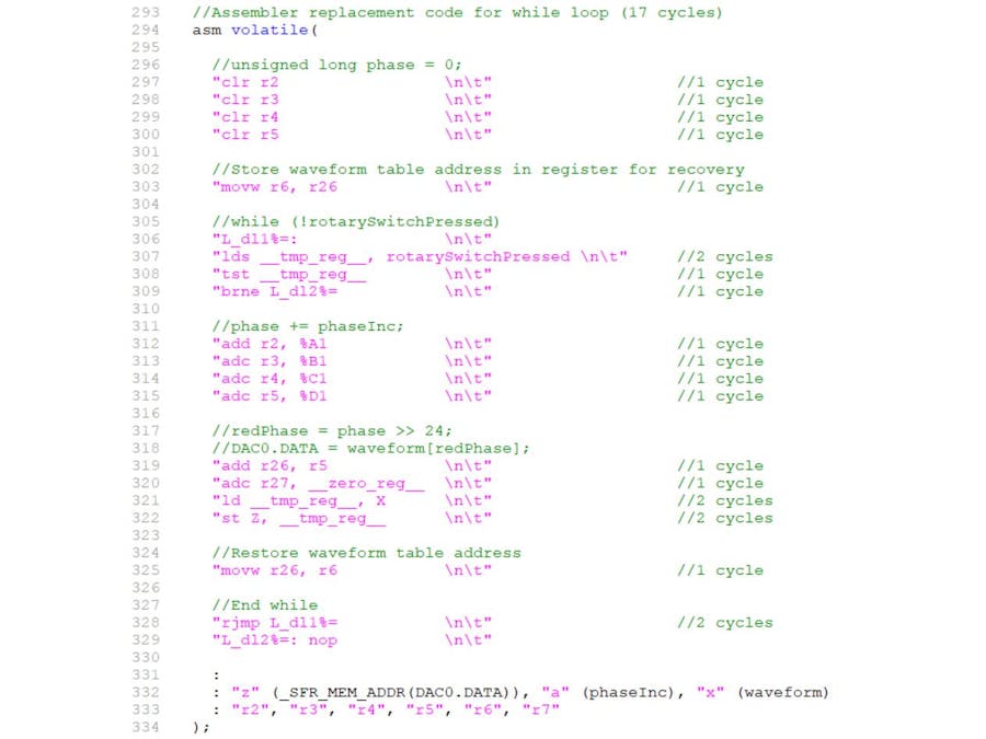
The Nitty Gritty - Initializing registersLet's start by looking at lines 294 to 302.
Registers r2 to r5 are used to store the unsigned long variable that in C was called phase. The clr instruction clears the register (makes it contain zero). Back in the [inputs] section, the address of the waveform table was initialized into the X pointer. The X pointer uses registers r26 and r27. Later on in the code, an index value will be added to the X pointer to create the address of a value in the waveform table that needs to be outputted to the DAC. A copy of the X register needs to be saved so it can be restored for the next iteration of the while loop. This is done by copying the X pointer to r6 and r7. The movw instruction moves a COPY of a pair of registers (in this case r26, r27) to another pair of registers (in this case r6, r7).
The Nitty Gritty - The while loop constructNext let's look at the while loop
To jump or branch to another location in the assembly code, there needs to be some way of telling the compiler where the destination location is. This is done using a label. In the while loop there are 2 labels. loop and done. A label definition is denoted by the colon character that immediately follows it.
The AVR_GCC compiler defines two special registers. These are __tmp_reg__ and __zero_reg__ which equate to registers r0 and r1 respectively. You should use the mnemonics rather than the actual register names incase the compiler changes which registers they refer to in the future. Use __tmp_reg__ to store temporary values. __zero_reg__ is initialized to zero at the start of the asm block. You will see why this is available later in the code. It goes without saying that you shouldn't use r1 to store your own variable or change its value.
Line 305 loads the temporary register with the value in the rotarySwitchPressed variable using direct addressing. You maybe wondering why this wasn't initialized in the [inputs] section. It is because this variable is set to true by the pin change interrupt when the rotary switch is pressed. If this was copied to a register at the start of the asm block, the value in the register will never change since it's only copied once and changing the value in memory wouldn't change the value in the register.
Line 306 tests the temporary register and sets the CPU's status flags. One of these flags is the Z flag which is set when the value in the register being tested is zero.
Line 307 branches if the temporary register is not equal to zero to line 327 which is after the end of the while loop. In other words, if the interrupt handler sets rotarySwitchPressed to true (a non zero value), the while loop will exit. Otherwise it will carry on executing line 308. The brne instruction (BRANCH IF NOT EQUAL TO ZERO) tests the Z flag in the CPU's status register which was set by the tst instruction (TEST) in the line before it.
At the end of the loop the rjmp instruction causes the the program to jump to the start of the while loop.
The Nitty Gritty - Inside the while loopFinally let's look at the assembly language code inside the while loop.
Remember that to refer to the second variable that appears in the [outputs] and [inputs] list, you use %1. This equates to the phaseInc variable which because it is an unsigned long or 32 bits in size, it is placed into 4 consecutive registers. However in general only a single register can be manipulated at a time. Because the compiler was told to load the phaseInc variable into any consecutive 4 registers in the range r16 to r23 ("a" constraint), there needs to be a way to refer to each of those 4 registers that make up the 32 bit value. This is done by modifying the reference with a letter. %A1 is the register that is the first of the 4 consecutive registers that make up %1 (the phaseInc variable) and holds the least significant 8 bits, %B1 is the register that holds the next significant 8 bits and so on.
When two base 10 numbers are added together such as say 64 + 18, the units column is added first. 4 + 8 part is 12. In the sum, 2 is placed the units position. Now the tens column is added plus the extra 1 which was the "carry" over of the units column since the sum of the units column exceeded 9. This results in 8 (6 + 1 + 1) being placed in tens column of the sum.
Looking at lines 310 to 313, the add instruction adds the least significant parts of phaseInc to phase. If the two numbers exceed the size of the 8 bit register, the "carry" flag inside the CPU is set. In line 311, the adc instruction (ADD WITH CARRY) adds the next two significant digits along with any carry that might of happened when the least significant bits were added together.
Now you can start to see why many programmers don't want to have anything to do with assembly language. It can be hard to write and understand.
So moving on, in C the temporary variable redPhase was loaded with the phase variable shifted right by 24 bits. In other words only the most significant 8 bits are used to index into the waveform table. In assembly language, there is no need to shift the phase variable (r2 to r5) 24 bits to the right because the most significant 8 bits are already sitting in r5. This means only r5 needs to be added to the start of the waveform table (X pointer) to obtain the address of the next value to output to the DAC. Because the X pointer is actually two registers r26 and r27, r5 is added to r26. Should the resultant sum exceed the size of r26, the CPU will set the carry flag in its status register. If this happens, r27 needs to have that carry added to it. This is where that always zero register that the compiler set up at the start of the asm block comes in handy. __zero_reg__ is added to r27 with any carry left over from adding r5 to r26 (lines 317 and 318).
Now that the X pointer points to the address in the waveform table, the value is obtained and placed into the __tmp_reg__ using indirect addressing via the X pointer (line 319). In the [inputs] section, the Z pointer was initialized with the address of the DAC.DATA. Line 320 uses the st (STORE) instruction to write __tmp_reg__ to the location pointed to by the Z pointer (indirect addressing).
The X pointer had its value changed in lines 317 and 318 when r5 was added to it. It now needs to be restored back to its correct value for the next iteration of the while loop. This is done in line 323. The X pointer is restored from r6 and r7 which was initialized back on line 301.
So was it worth itI guess the best way is to judge for yourself.
The while loop written in C took 57 CPU cycles. That same loop written in assembly language takes 17 CPU cycles.
While many programmers frown when even the phrase "assembly language" is mentioned, it can be a useful resource when it comes to increasing speed or reducing program size. The learning curve is steep but the results do speak for themselves.

Comments
Please log in or sign up to comment.