Testing transistors and diodes while they are soldered on a board can be difficult as they are often shunted to some extent by other components; usually resistors, capacitors or a combination of both.
This in-circuit tester will allow you to test PN junctions for shorts, open circuits and polarity.
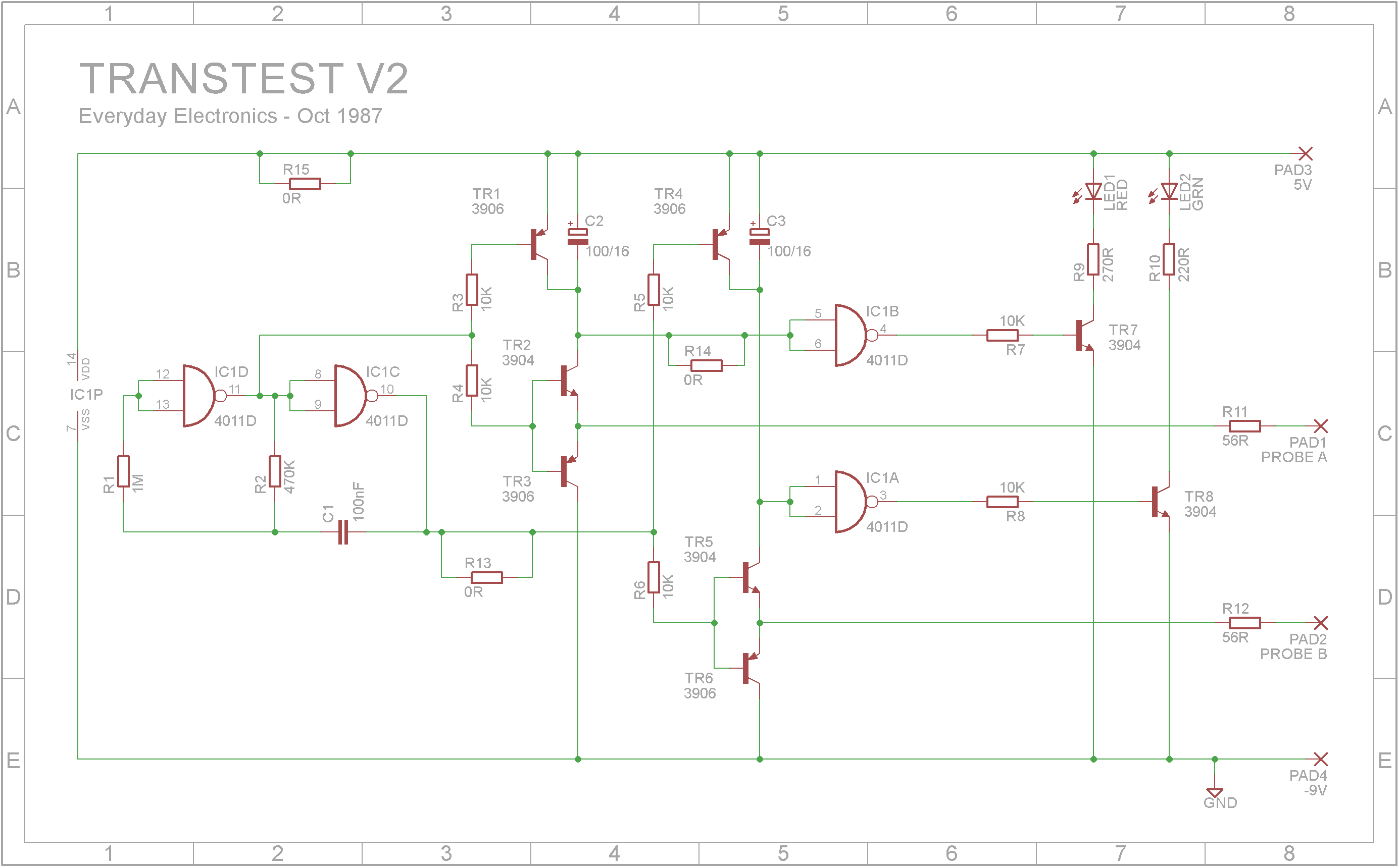
At first the circuit might seem quite complicated, but if you break it down into its logical parts, it is actually quite simple.
The oscillator provides generates two square waves each being 180 degrees out of phase with the other. The frequency is around 10Hz.
When the input from the oscillator is LOW, TR3 is ON and TR2 is OFF and the probe is grounded through R11 and TR3. TR1 also switches on and discharges C2. Pin 4 of IC1B goes LOW and TR7 is OFF and the LED is extinguished.
When the input from the oscillator is HIGH, TR1 is OFF, TR2 is ON, TR3 is OFF and C2 is able to charge through TR2 and R11 when the probe is grounded (via the device under test to the other probe), C2 will charge and pin 4 of IC1B goes HIGH and TR7 switches ON lighting up the LED.
When the two probes are used together, both LEDs will light up when DUT (device under test) is shorted, neither will light up if the DUT is open circuit and either the RED or GREEN led will light up based on the polarity of the PN junction.
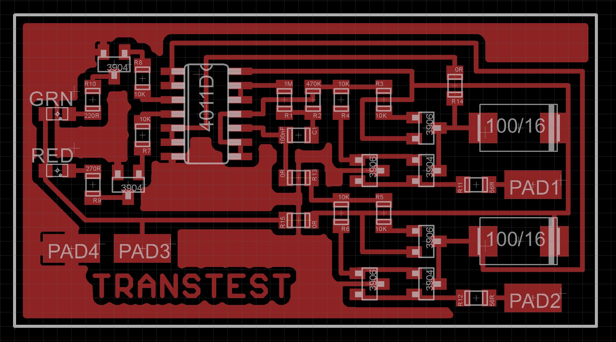
BuildI chose to use SMD components exclusively. This meant the final PCB was small enough to be glued directly onto the 4.5V 3xAA battery holder with on/off switch.
The Eagle files for the PCB have been included should you wish to get them commercially made or you can choose to make them yourself.
I used the Toner method to make mine.
When soldering SMD components, it is easier to use solder paste in syringe form rather than solder from a reel.
For a simple diode, the probe (or LED) associated with the cathode will flash.
A PNP transistor behaves like two diodes, emitter to base, and collector to base, the base in each case being the cathode. With an NPN type these apparent diodes are reversed, the cathodes being the emitter and collector whilst the base acts as common anode. An apparent open circuit should exist between emitter and collector. Through these tests it is usually possible to identify the base, whether the device is PNP. or NPN., and if there is a reasonable chance of it being healthy.
In most cases it will be possible to carry them out without removing the component from circuit (switch off first though!), although shunt components may sometimes produce false indications.
The tester should not respond to resistors above about three hundred ohms or capacitors below about 47uF. Testing is also possible with Zener diodes down to 2.7V; these behave like ordinary diodes with clear indication of the cathode. LEDs unfortunately do not give reliable results, although most do light dimly on the probe current, which may prove useful in some instances.


Comments
Please log in or sign up to comment.